


News Center
—— NEWS CENTER ——
Xi'an Shenghongchuang Instrument Co., Ltd.
Contact: Mr. Zhang
Mobile: 15529283736
Email: shc-sensor@qq.com
Address: Fortune Building, Sanqiao Street, Xixian New Area, Xi'an, Shaanxi Province
Operating Logic and Terminal Identification of Four-Wire Differential Pressure Transmitters
Four-wire differential pressure transmitters typically use separate power supply and signal output circuits. Common terminal markings are “Power +, Power -, Signal +, Signal -”, or alternatively “V+, V-, OUT+, OUT-”. Unlike two-wire 4-20mA loop-powered devices, four-wire products are powered by an independent DC supply, while their output terminals provide standard analog signals to PLCs, DCSs, intelligent digital display instruments, or data acquisition modules.
In industrial applications, four-wire differential pressure transmitters are commonly powered by 24VDC. Some products also support 12VDC, 15VDC, or wide-voltage 18-36VDC input. Before installation, wiring relationships must not be determined by wire color alone; the product nameplate, manual, and wiring diagram inside the terminal cover shall prevail. Different manufacturers may assign different meanings to red, black, yellow, blue, and other wires. Reversed power polarity may prevent normal operation and, in severe cases, damage internal protective components.
A differential pressure transmitter measures the pressure difference between the high-pressure and low-pressure sides, and its output normally changes linearly from the lower range limit to the upper range limit. For example, for a range of 0-10kPa and an output of 4-20mA, 0kPa corresponds to 4mA, 5kPa corresponds to 12mA, and 10kPa corresponds to 20mA. Where the range has negative suppression, positive elevation, or a bidirectional differential pressure range, the output relationship shall be verified according to the actual settings.
The advantage of a four-wire configuration is that its output load capability is relatively well defined, and power supply voltage fluctuations have less direct impact on the output circuit. It is suitable for applications such as long-distance transmission, independent power supply, and on-site signal isolation. However, “independent power supply” does not mean wiring can be handled arbitrarily. Signal reference ground, shield termination, and grounding methods still determine the final stability of the system.
Common Four-Wire Terminals and Wiring Functions
Engineering personnel should first confirm the output type. Although 4-20mA is the most common configuration for differential pressure transmitters, models with 0-10V, 1-5V, RS485, or relay alarm outputs are also available. 4-20mA is suitable for most remote transmission applications and generally offers better voltage-drop tolerance and common-mode interference resistance than voltage-type outputs. In contrast, 0-10V output is more sensitive to cable resistance, electromagnetic induction, and grounding differences.
For current-type outputs, the signal “+” terminal is generally connected to the positive terminal of the control system analog input, and the signal “-” terminal is connected to the analog input negative terminal or common terminal. If the PLC input module is passive, loop power shall be provided according to the module instructions or the correct external loop wiring method shall be used. If the module is active, duplicate power supply with the transmitter output must be prevented.
For voltage-type outputs, it is necessary to confirm whether the common reference terminals of the transmitter output and receiving end are compatible. Connecting a current output directly to a voltage input channel, or connecting a 0-10V output to a 4-20mA input channel, will cause abnormal readings. Where signal conversion is required, matched resistor sampling, signal isolators, or dedicated conversion modules shall be used.
Xi'an Shenghongchuang Instrumentation Co., Ltd. typically provides differential pressure transmitter output solutions according to users' power supply conditions, control system interfaces, cable distances, and on-site interference levels during project support. For non-standard ranges, special fittings, display heads, or special signal interface requirements, technical confirmation should be completed before ordering and installation to avoid on-site rework.
Factors Affecting Signal Stability During Long-Distance Transmission
The core issue in long-distance wiring is not merely whether the cable is connected, but whether the signal can remain accurate, continuous, and traceable after reaching the control end. When differential pressure transmitters are used to measure air pressure, filter differential pressure, liquid level differential pressure, flow restriction devices, pipeline pressure drop, and similar parameters, even a 0.2mA output drift may cause incorrect judgments by the control system.
The 4-20mA signal offers certain advantages for remote transmission. With suitable cable cross-sectional area and loop load meeting requirements, stable measurement results can still be obtained over distances of several hundred meters. By comparison, 0-10V output is more prone to low readings at the receiving end due to line voltage drop. Therefore, 4-20mA solutions are generally preferred for transmission distances exceeding 100m, areas with dense variable-frequency drives, or workshops with complex electromagnetic environments.
Conductor resistance causes voltage loss, but for four-wire 4-20mA outputs, the more critical factor is confirming that the receiving device input impedance and total line load are within the transmitter's allowable range. If output driving capability is insufficient, the actual current cannot reach the 20mA full-scale value, resulting in a low upper range limit or fluctuations in the high-range data at the control end.
In addition to cable length, the cable routing path is also important. If signal cables are routed in parallel for extended periods with 380V power lines, variable-frequency drive output cables, welding machine cables, or high-power motor cables, induced interference may be superimposed on the analog signal. In engineering practice, instrument signal cables should be routed separately from power cables, with a recommended parallel spacing of more than 300mm. Where avoidance is not possible, vertical crossing may be used to reduce coupling effects.
Cable Selection, Shielding, and Grounding
Copper-core shielded twisted-pair cables are recommended for long-distance transmission. The twisted-pair structure reduces differential-mode interference from external magnetic fields on the two signal conductors, while the shielding layer helps reduce high-frequency electromagnetic noise entering the circuit. Common instrument cable specifications include 2×0.75mm², 2×1.0mm², and 2×1.5mm². Actual selection should consider distance, current load, ambient temperature, and mechanical protection requirements.
The shielding layer is generally grounded at one end, typically connected to instrument ground or functional ground at the control cabinet side. The shield at the field transmitter end should be properly insulated. Dual-end grounding may form a ground loop when there is a potential difference between both ends, allowing 50Hz power-frequency interference or equipment leakage current to enter the signal system and causing periodic fluctuations on the PLC display.
Transmitter enclosure grounding and signal shield grounding must not simply be treated as the same. Protective grounding of a metal enclosure primarily serves personnel safety, electrostatic discharge, and electromagnetic compatibility, while the signal shield is used to suppress interference during transmission. In high-interference environments, the transmitter enclosure may be reliably connected to protective earth while the signal shield is terminated at one end as required by the system design.
In complex sites such as chemical, energy, metallurgy, and building materials facilities, junction boxes, cable glands, and terminal blocks also affect long-term stability. Junction boxes with matching protection ratings should be used in outdoor or humid areas, and cable entries should be sealed to prevent condensate from penetrating along the conductors. Terminal screws should be tightened securely but not excessively to avoid broken strands or terminal damage.
Standard Wiring Procedure and Pre-Commissioning Inspection
Before wiring, disconnect the relevant power supply and confirm that the process-side high-pressure and low-pressure tapping valves and equalizing valve are in appropriate positions. For differential pressure transmitters already installed on pipelines or equipment, electrical wiring and impulse line operations should be managed separately. Do not remove fittings or open venting and draining points before confirming pressure conditions.
The first step is to verify the model and parameters, including range, power supply range, output signal, accuracy class, process connection, and protection rating. For example, for a product with an accuracy of 0.5%FS and a range of 0-20kPa, its allowable basic error is directly related to the range. If the actual on-site differential pressure remains below 2kPa for an extended period, the range should be reassessed to avoid insufficient low-range resolution.
The second step is to complete the power supply circuit and signal circuit wiring. It is recommended to connect the power negative and signal negative terminals first, followed by the positive terminals, while leaving adequate slack for future maintenance. Each cable should be clearly identified with wire markers or labels, and the corresponding tag number should also be marked at the control cabinet end. This can significantly reduce troubleshooting difficulty when multiple instruments are installed together.
The third step is power-on inspection. Use a multimeter to measure the supply terminal voltage and confirm that it is within the allowable transmitter range. Then measure the output current in series or with a clamp meter to confirm whether it is close to 4mA near zero. If an intelligent digital display or PLC display is used, also verify the displayed value, engineering unit, decimal places, and range conversion parameters to prevent situations where “the field current is correct but the upper-level display is incorrect”.
4-20mA and Engineering Value Conversion Verification
For linear 4-20mA output, the engineering value can be calculated using the formula: actual measured value = lower limit value + (measured current - 4mA) ÷ 16mA × range span. This method can be used for quick on-site verification of conversion results for transmitters, PLC analog modules, and display instruments, particularly for cross-validation during commissioning.
Taking a 0-10kPa differential pressure transmitter as an example, an output of 8mA corresponds to a differential pressure of 2.5kPa; 12mA corresponds to 5kPa; and 16mA corresponds to 7.5kPa. If the control system displayed value differs significantly from these reference points, first check whether the module range is set to 4-20mA rather than incorrectly set to 0-20mA.
For differential pressure measurements with elevation or suppression, the zero point does not necessarily correspond to a physical differential pressure of zero. For example, in liquid level differential pressure measurement, positive or negative elevation may be set to offset impulse line static pressure or installation height effects. In this case, 4mA represents the configured lower range limit, rather than simply meaning that “the pressures on both sides are completely equal”.
After commissioning is completed, record the supply voltage, zero output, full-scale output, control system displayed value, and grounding method. For critical positions, coordinated commissioning records may be made at 4mA, 12mA, and 20mA. After baseline data are established, subsequent drift, fluctuation, or distortion can be traced more quickly to the sensor itself, the wiring, or the control end.
Key Items to Verify Before Commissioning
Confirm that the process connection directions of the high-pressure and low-pressure sides are correct. If the high-pressure and low-pressure sides are reversed, the transmitter may produce reverse output changes. For models that do not support bidirectional differential pressure, the device may also remain in a low-limit alarm state for extended periods. The “H” and “L” markings on the piping should be confirmed together with process drawings, instrument tag numbers, and on-site medium flow direction.
Check cable insulation, shield continuity, and terminal tightness. Details such as excessively exposed copper conductors, shields contacting the enclosure, water accumulation in junction boxes, and oxidized crimp terminals are often sources of intermittent signal abnormalities after several months of operation. For equipment with significant vibration, terminal tightness should be rechecked during maintenance intervals.
Confirm that control system alarm thresholds are set appropriately. Values below 4mA can often be used to identify open circuits, faults, or lower-limit overrange conditions, while values above 20mA can be used to identify upper-limit abnormalities. However, the specific fault current range must be based on product technical parameters. Not all conditions below 4mA should be directly judged as sensor damage.
Before formal commissioning, compare the on-site process condition with the transmitter output trend. For example, filter differential pressure is generally low immediately after filter replacement and gradually increases with operating time. If the trend is completely opposite to the equipment operating pattern, recheck the pressure tapping locations, impulse line blockage, and high-pressure/low-pressure side connections.
Common Fault Symptoms and Remote Transmission Troubleshooting
When the control end continuously displays 0mA, 0V, or no valid data, first check whether 24VDC power is available, then inspect fuses, circuit breakers, terminal blocks, and cable continuity. Even if power supply is normal, an open signal wire in a four-wire product will cause no reading at the receiving end. Therefore, the power terminals and output terminals should be measured separately rather than checking only one circuit.
When the signal remains fixed near 4mA, the actual differential pressure may be close to the lower range limit, or the pressure difference between the high-pressure and low-pressure sides may not be established. Other possible causes include blocked impulse lines, mismatched range settings, or incorrectly configured output parameters. During troubleshooting, first determine whether the process is actually at a low differential pressure condition, then verify the transmitter using a standard pressure source or process calibrator.
When PLC values fluctuate frequently while field pressure is stable, interference and grounding issues should be investigated first. Observe whether the transmitter's local current is stable: if the local current is stable but the PLC fluctuates, the issue is likely in the cable, terminals, isolator, or input module; if the local output itself fluctuates, also check power quality, sensor installation vibration, and process pressure pulsation.
When remote readings are generally high or low, measure the current at the transmitter output terminal and control cabinet input terminal respectively. If the current at both locations is consistent but the display deviation is obvious, the issue is usually with PLC range, engineering units, or A/D module parameters. If there is a large difference between the two locations, inspect the signal circuit wiring, isolation module condition, and line contact resistance.
Establishing a Maintainable Differential Pressure Measurement System
Stable long-distance signals cannot be achieved by a single high-precision sensor alone. They result from transmitter selection, standardized wiring, correct grounding, proper routing, and periodic maintenance. For continuous production systems, it is recommended to include differential pressure transmitters in preventive maintenance plans and conduct output verification every 6 months or 12 months according to operating conditions.
During selection, priority should be given to defining the medium properties, differential pressure range, static pressure rating, overload capacity, temperature conditions, installation location, output method, and transmission distance. Application conditions vary greatly among machinery manufacturing, chemical energy, environmental monitoring, and automated production lines. Using a single standard model while ignoring actual operating conditions can easily result in inadequate measurement accuracy or excessive maintenance frequency.
Shaanxi Qinkong Sensor Technology Co., Ltd. provides supporting products and customized services for industrial measurement and control requirements involving pressure, liquid level, differential pressure, and other parameters, relying on standardized production, accuracy calibration, and finished-product testing processes. For complex operating conditions, suitable differential pressure ranges, material configurations, signal outputs, and anti-interference solutions can be determined based on the on-site medium, installation structure, and control interface.
If a four-wire differential pressure transmitter is required for an existing system, it is recommended to compile information on on-site supply voltage, control system input type, transmission distance, process differential pressure range, and installation environment, and contact the technical personnel of Xi'an Shenghongchuang Instrumentation Co., Ltd. for parameter verification in order to obtain wiring and selection recommendations better suited to on-site requirements.
Related Recommendations
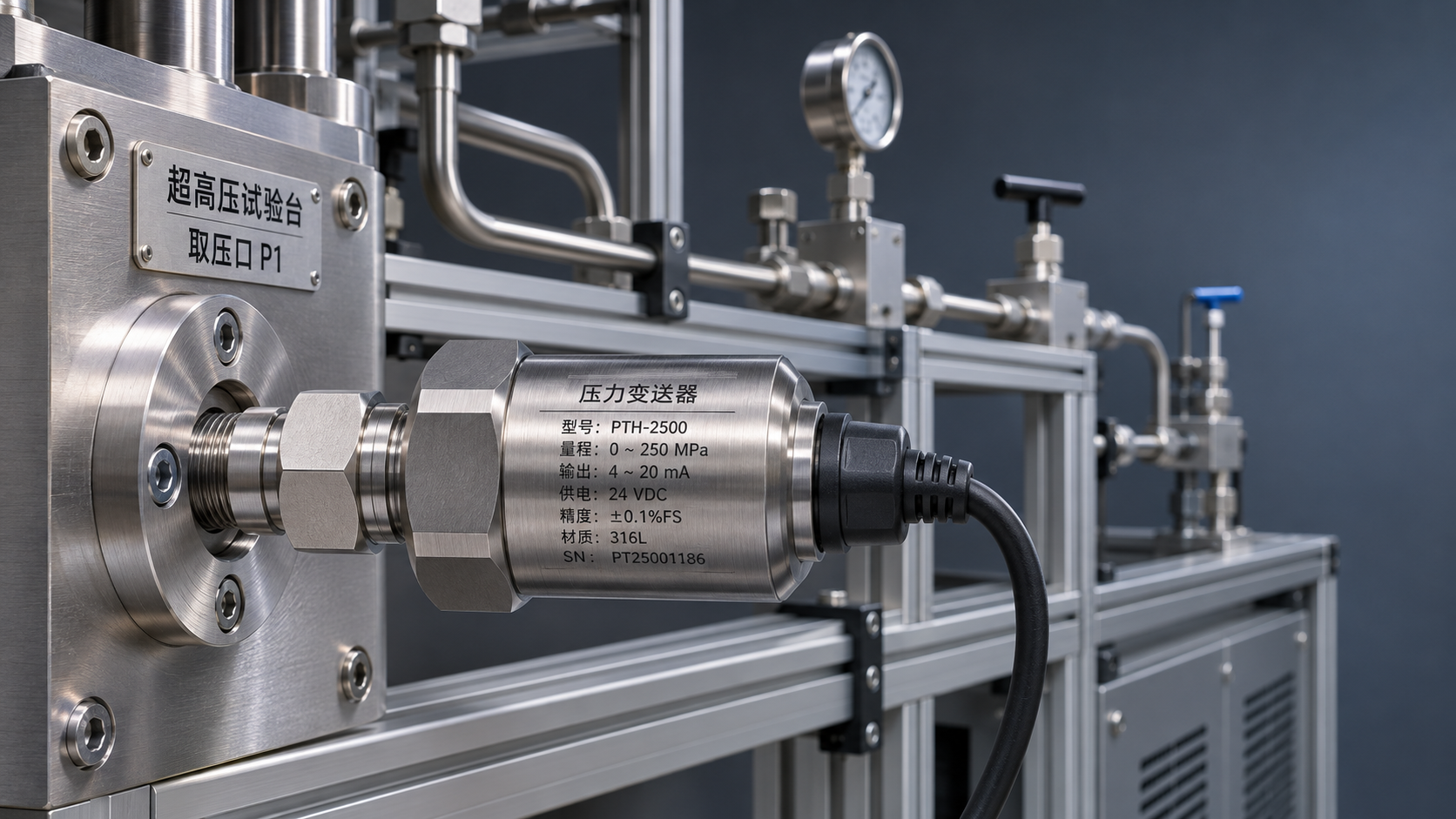
 How should mounting connections and safety margins be determined for a high-pressure transmitter used in ultra-high-pressure equipment?
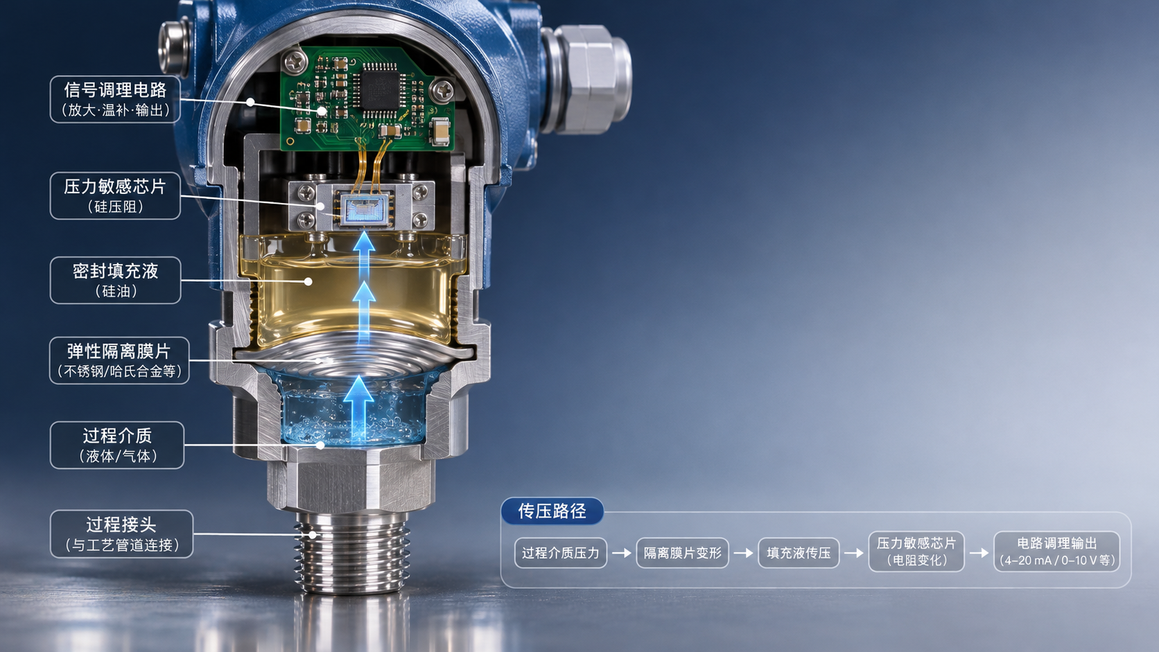
 How an Oil-Filled Pressure Transmitter Works: Pressure Transfer Through the Isolation Diaphragm and Fill Fluid
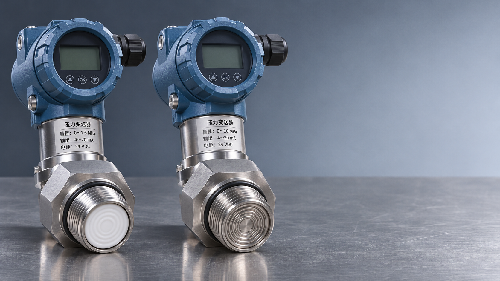
 Ceramic-Core vs. Oil-Filled Pressure Transmitters: How to Choose Based on Corrosion Resistance and Overload Capacity
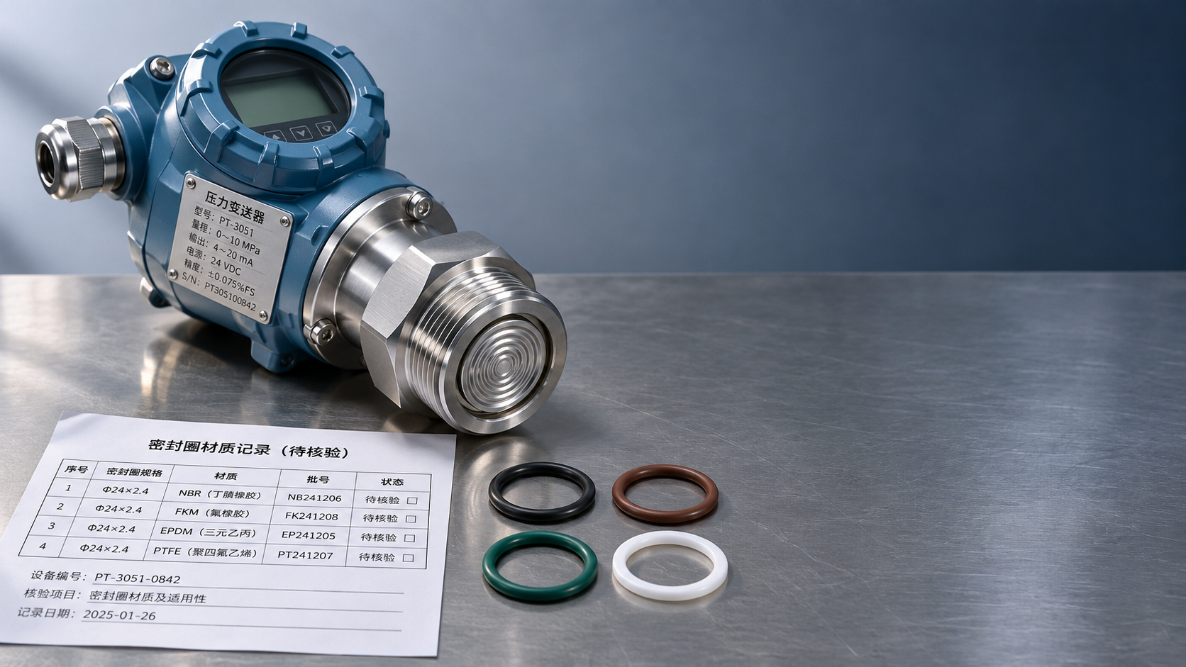
 How should the wetted parts of a 316L pressure transmitter be inspected for corrosive media?