


News Center
—— NEWS CENTER ——
Xi'an Shenghongchuang Instrument Co., Ltd.
Contact: Mr. Zhang
Mobile: 15529283736
Email: shc-sensor@qq.com
Address: Fortune Building, Sanqiao Street, Xixian New Area, Xi'an, Shaanxi Province
How does an oil-filled sensing element pressure transmitter isolate the process medium and transmit pressure accurately? Understanding how the isolation diaphragm, fill fluid, and sensing chip work together helps technical personnel determine whether an instrument is suitable for the actual medium, temperature, and pressure conditions.
I. Basic Structure of an Oil-Filled Sensing Element
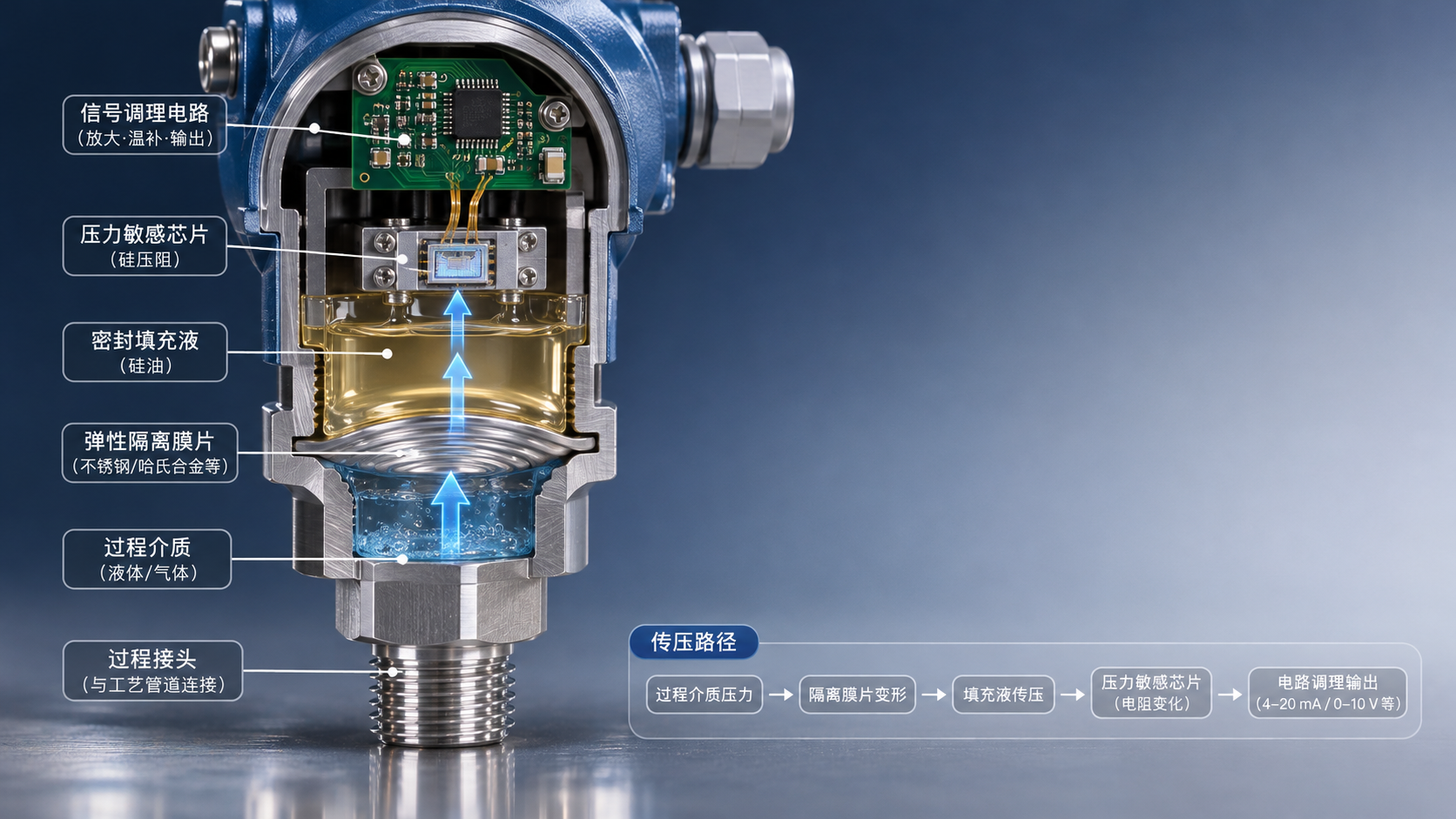
An oil-filled sensing element pressure transmitter typically consists of a process connection, isolation diaphragm, sealed fill fluid, pressure-sensing chip, and signal-processing circuit. Different manufacturers may use different structures and packaging methods, but the basic purpose is to convert process pressure into an electrical signal that can be used by a control system.
The medium being measured first contacts the isolation diaphragm, not the internal sensing chip directly. The back of the diaphragm contacts the fill fluid in the sealed cavity. Pressure is transmitted through the fill fluid to the chip, causing an electrical change related to the pressure.
“Oil-filled” means that a fluid suitable for pressure transmission is sealed inside the sensing element cavity. It does not mean that the transmitter needs to be refilled with oil periodically during use. The type of fill fluid, sealing process, and operating temperature range should be confirmed in the specific product documentation.
What Does the Isolation Diaphragm Do?
The isolation diaphragm is an elastic metal membrane, usually made of corrosion-resistant material. When the medium pressure acts on its surface, the diaphragm undergoes a slight deformation and transfers the force to the fill fluid on the other side.
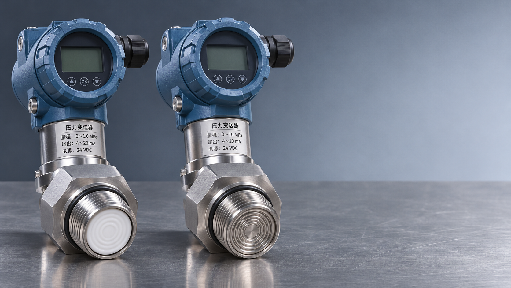
The diaphragm separates the medium being measured from the sensing chip, reducing the risk of direct contact between the medium and the chip or internal structures. However, “isolation” does not mean that the transmitter is suitable for all media. The diaphragm, welds, and seals must each meet the relevant corrosion-resistance requirements.
The diaphragm’s thickness, shape, and effective area affect its stiffness and response characteristics. A diaphragm that is too rigid may reduce sensitivity when measuring low pressures. Deformation caused by overpressure, impact, or corrosion may also cause zero drift or even failure.
II. How Pressure Is Transmitted Through the Fill Fluid
When the process pressure changes, the isolation diaphragm moves slightly, changing the pressure of the fill fluid in the sealed cavity. Within the normal operating range, the fill fluid is approximately incompressible and transmits the pressure change to the surface of the sensing chip.
Pressure transmission does not involve continuous fluid flow through a pipe. In a properly sealed sensing element, only a very small displacement of the diaphragm and chip is needed for the cavity pressure to change in response to the external pressure.
The fill fluid also affects temperature suitability, dynamic response, and long-term stability. Common fill fluids include silicone oil. The specific choice should take into account the operating temperature, risk of contact with the medium, and product design; the term “oil-filled” alone is not enough to determine suitability.
From Pressure Changes to a Standard Signal
A common example is a piezoresistive sensing element. The fill fluid applies pressure to a silicon sensing diaphragm. As the diaphragm deforms under the applied force, the resistance of its piezoresistive elements changes. A bridge circuit converts this change into a weak voltage signal.
The transmitter circuit amplifies the raw signal, compensates for temperature, and applies any necessary linearity correction before converting it into an output that the control system can read. Common output formats include a 4–20 mA current signal; other interfaces may also be available depending on the model.
For example, for a transmitter with a 0–1 MPa range and a linear 4–20 mA output, ideally 0 MPa corresponds to 4 mA, 1 MPa to 20 mA, and 0.5 MPa to 12 mA. Actual readings are still affected by the accuracy class, temperature, and installation conditions.
III. Factors That Can Affect Measurement Results
Temperature changes may alter the volume of the fill fluid and may also change the stress state of the diaphragm and chip, causing shifts in zero or span. These effects should be evaluated against the product’s temperature error specifications, particularly for low-range measurements.
Residual gas in the sealed cavity increases the compressibility of the system and may affect low-pressure measurements and response consistency. Filling, degassing, and sealing quality are therefore important control points in the manufacture of the sensing element.
In addition, process pressure pulsation, water hammer, crystallization and blockage, deposits on the diaphragm, and electromagnetic interference can all affect field readings. If readings are abnormal, check the operating conditions, installation location, power supply, and wiring as well; do not assume that the sensing element itself is damaged.
Considerations for Vacuum and High-Temperature Conditions
For vacuum applications, confirm that the sensing element and fill fluid are suitable for the relevant absolute pressure range. The performance of some products may be limited under combinations of low absolute pressure and high temperature, so do not select a model based solely on specifications at atmospheric pressure.
A high-temperature medium does not mean that the sensing element can be used continuously above its rated temperature. Depending on site conditions, heat dissipation, isolation, or a remote-mounting structure may be considered. Confirm the allowable temperature, response speed, and additional error for the specific solution.
If the fill fluid could contaminate the measured material, also assess the potential consequences of diaphragm damage and confirm the fill-fluid material and suitability requirements with the supplier. Applications in food, pharmaceutical, and other industries should also be verified against the applicable regulations and process standards.
IV. What to Confirm When Selecting and Installing
First, specify whether the measurement is gauge pressure, absolute pressure, or differential pressure, and confirm the normal operating pressure, possible peak pressure, and overload conditions. If the pressure type and range do not match the application, the output may be normal but still fail to represent the process variable of interest.
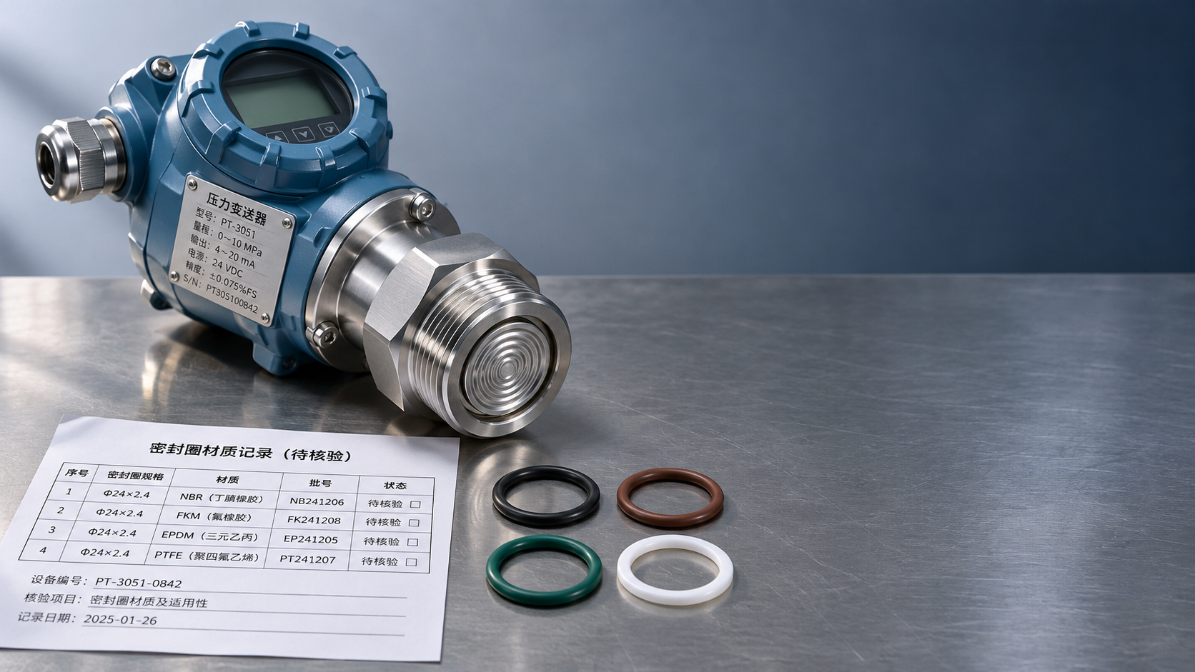
Next, verify the compatibility of the medium with the diaphragm, connection, and seals, and confirm the process connection, power supply, output signal, and protection requirements. Corrosive, viscous, or crystallizing media may require special wetted materials or a specific diaphragm structure.
During installation, avoid touching the diaphragm with hard objects and follow the product instructions for the tightening location and torque. After commissioning, check the zero point and output under safe conditions, and establish a calibration interval appropriate to the usage frequency and operating risks.
Distinguishing Process Pressure Measurement from Mechanical Force Measurement
Oil-filled sensing element pressure transmitters are primarily used to measure the pressure of fluid or gas media. Weighing, press-fitting, and mechanical load detection generally require force sensors. Although both involve converting an applied force into an electrical signal, their installation methods, range units, and calibration methods differ, so they cannot be used interchangeably.
For example, LCS-C2A Chinese-Made Spoke-Type Load Cell and Force Sensor, Round with Square Base, Pressure Sensor is used for force measurement and control. Available in 5 kg–20 t capacities, it can withstand both tension and compression and is suitable for applications such as weighing and mechanical load detection. It is not an oil-filled sensing element for directly measuring pressure in a pipeline.
To determine a pressure transmitter solution, provide Xi’an Shenghongchuang Instrument and Meter Co., Ltd. with the medium name, normal and peak pressures, medium temperature, process connection, and desired output signal. Technical personnel can then verify the materials and range for the specific operating conditions.
Related Recommendations
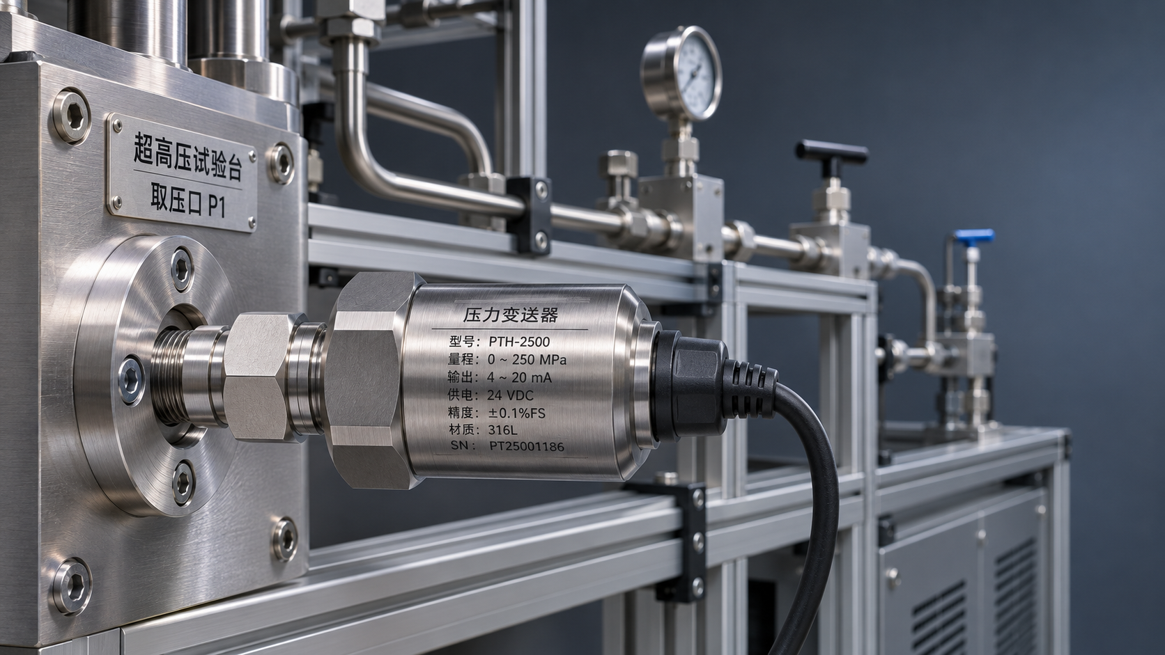
 How should mounting connections and safety margins be determined for a high-pressure transmitter used in ultra-high-pressure equipment?
 How an Oil-Filled Pressure Transmitter Works: Pressure Transfer Through the Isolation Diaphragm and Fill Fluid
 Ceramic-Core vs. Oil-Filled Pressure Transmitters: How to Choose Based on Corrosion Resistance and Overload Capacity
 How should the wetted parts of a 316L pressure transmitter be inspected for corrosive media?