


News Center
—— NEWS CENTER ——
Xi'an Shenghongchuang Instrument Co., Ltd.
Contact: Mr. Zhang
Mobile: 15529283736
Email: shc-sensor@qq.com
Address: Fortune Building, Sanqiao Street, Xixian New Area, Xi'an, Shaanxi Province
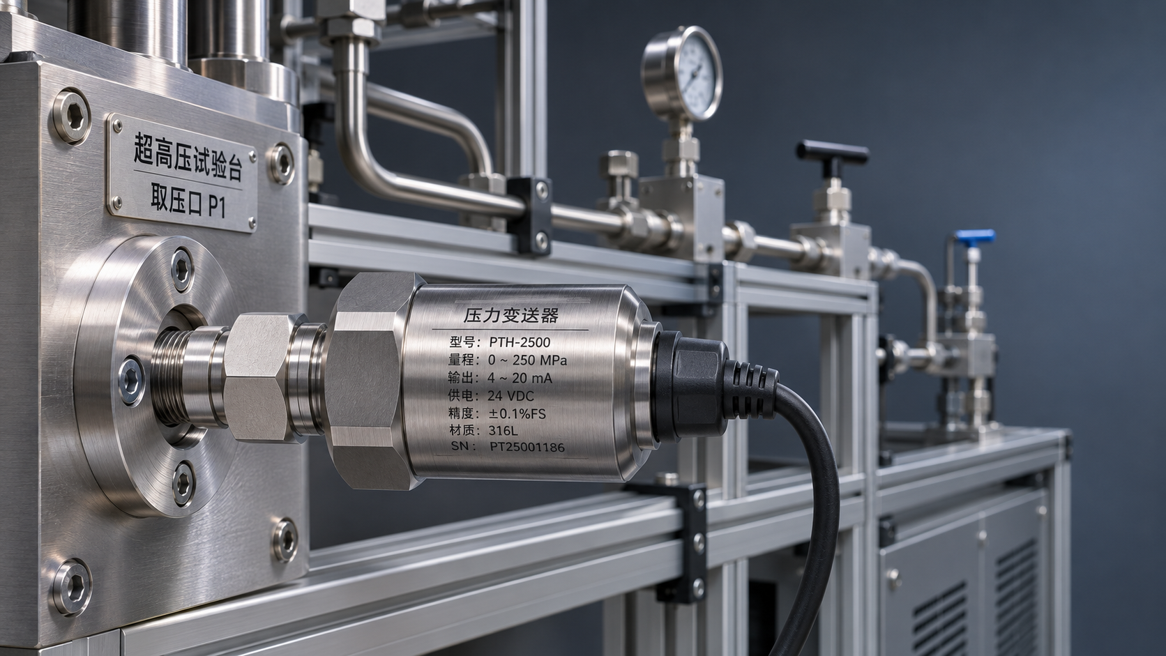
When selecting a high-pressure pressure transducer for ultrahigh-pressure equipment, connector compatibility and adequate safety margins directly affect measurement reliability and personnel safety. Selection should not be based solely on the measuring range and thread dimensions; pressure peaks, the medium, temperature, and the pressure ratings of the entire connection assembly must also be considered.
1. First determine the actual operating conditions and pressure limits
Distinguish between operating pressure, peak pressure, and set pressure
First, collect the equipment’s normal operating pressure, maximum operating pressure, start-stop frequency, and pressure-holding time. For equipment such as hydraulic presses and pressure-boosting test benches, also consider pressure reversal, rapid valve closure, and depressurization, as short-term pressure peaks may exceed the stable pressure shown by the instrument.
For example, a normal operating pressure of 100 MPa does not mean that a 100 MPa range is sufficient. If measurements or reliable calculations confirm transient peaks of 130 MPa, that peak must be taken into account during selection, and the transducer’s dynamic response and allowable pressure conditions must also be verified.
Also clarify whether the pressure reference is gauge or absolute pressure, and confirm the type of medium, maximum and minimum temperatures, and whether corrosion, particulates, or a gas-liquid mixture are present. This information affects the wetted materials, sealing method, and installation method.
2. Match the installation connector to the complete connection assembly
Matching threads do not necessarily mean the connectors are interchangeable
When selecting a connector, check the thread standard, size, pitch, direction, effective engagement length, and sealing location. Markings such as M20×1.5 specify only some interface details; the fact that the threads can be screwed together, or that they look alike, is not enough to establish that the two ends can seal reliably.
In ultrahigh-pressure connections, sealing may rely on a cone, spherical surface, end face, or specialized metal-sealing structure. Even when connectors from different manufacturers have similar nominal dimensions, their sealing angles, contact-surface dimensions, and machining requirements may differ. Refer to interface drawings confirmed by both parties.
Before installation, inspect the surfaces of the female port, connector, and sealing faces, and prevent scratches, impact damage, and foreign-material contamination. Follow the manufacturer’s instructions for the applicable connection system regarding tightening torque, lubrication requirements, and whether sealing components may be reused.
Common interface verification items
3. The safety margin must cover the entire pressure-bearing chain
Measuring range, overload pressure, and burst pressure are not interchangeable
The measuring range defines the range over which the instrument’s specified performance applies. Allowable overload pressure describes the overrange pressure the product can withstand under specified conditions, while burst pressure relates to the structural failure limit. These terms have different meanings: burst pressure must not be treated as normal operating pressure, and the instrument must not be assumed to maintain its rated accuracy during an overload.
During selection, ensure that normal measured values fall within a suitable range and that the anticipated maximum pressure and transient peaks meet the manufacturer’s allowable conditions. The required margin depends on pressure cycling, shock duration, temperature, medium, and applicable standards; a single fixed multiplier cannot be applied universally.
For equipment with a normal operating pressure of 100 MPa and possible peaks of 130 MPa, suppose a range of 0–160 MPa is selected. The normal pressure is about 62.5% of full scale, and the peak is about 81.25%. This is only an example of range utilization; it does not mean that the model or the complete system is safe. Dynamic performance, fatigue life, and the rated conditions of all connection components must also be verified.
Check each component against the weakest link
The complete pressure-bearing chain typically includes the equipment pressure port, female port, connector, adapter, valve, pressure line, and transducer. Each component must have a pressure rating suitable for the actual temperature and medium. If any link is inadequate, increasing the transducer’s measuring range will not compensate for it.
Pay particular attention to adapters: they may add sealing points or alter the way loads are applied. If an adapter is necessary, confirm that its design has been verified, and check the interfaces at both ends, pressure rating, and installation clearance. Avoid on-site assembly using parts of unknown specifications.
Overpressure protection devices should be assessed separately as part of the equipment design. A pressure transducer is primarily intended for measurement; its output signal or overload capability alone cannot replace appropriately designed safety protection measures.
4. Account for dynamic measurement and equipment integration
Pressure shocks and installation location
Where possible, avoid locating the pressure tap in areas subject to strong vibration, high-temperature radiation, or the accumulation of contaminants. Long impulse lines, throttling structures, or damping devices may reduce pressure shocks, but they can also alter measurement response. If rapid peaks need to be captured, assess the response capabilities of the sensor, piping, and data acquisition system together.
Where pulsation or frequent pressure cycling occurs, confirm with the manufacturer the applicable cycling conditions and fatigue performance, in addition to static pressure resistance. Do not disregard recurring high peaks simply because the long-term average pressure is low.
The equipment may also need to monitor mechanical quantities such as hydraulic cylinder stroke and workpiece deformation. In this case, displacement measurements can be analyzed together with pressure curves to assess operating conditions, but displacement signals cannot replace pressure verification or safety protection for pressure-bearing components.
Selecting complementary displacement measurement
China-made TWR differential rod-type linear displacement sensor, spring-return inductive sensor can be used for relative displacement measurement and for measuring mechanical quantities that have first been converted into displacement changes. It is suitable as a complementary option for equipment condition data acquisition.
This product offers a 12–24 VDC power supply, a range of analog output options, an operating temperature range of -20 ℃ to 120 ℃, and a warm-up time of 5 minutes. When configuring the system, verify that the selected output specification, range, mounting dimensions, and site temperature meet the equipment requirements.
When acquiring pressure and displacement data together, also confirm the sampling frequency and time-synchronization method for both signal channels to prevent acquisition delays from distorting the correspondence between the curves. Actual measurement performance must be verified through commissioning of the complete equipment.
5. Prepare selection documentation and complete installation acceptance
Document parameter verification in drawings and records
Before installation, personnel with appropriate qualifications and experience should confirm the interface drawings, material certificates, and product technical documentation, inspect the cleanliness of wetted surfaces, and assemble the components in accordance with the manufacturer’s instructions. The pressure testing plan, isolation measures, and operating procedures must comply with the standards applicable to the equipment and on-site safety management requirements.
After commissioning, schedule leak checks, zero-point checks, and periodic calibration according to operating conditions. If abnormal pressure fluctuations, connector leakage, or signal drift occurs, first shut down the equipment in accordance with its procedures, isolate it, and confirm that it has been fully depressurized before inspection. Never disassemble components under pressure.
When requesting a selection recommendation, provide Xi'an Shenghongchuang Instrumentation Co., Ltd. with the normal and maximum pressures, known peaks, medium, temperature, pressure reference, interface drawings, and output signal requirements, and specify the pressure cycling conditions and installation space. Technical personnel can then verify compatibility between the transducer and the complete connection assembly before determining the specific configuration.
Related Recommendations
 How should mounting connections and safety margins be determined for a high-pressure transmitter used in ultra-high-pressure equipment?
 How an Oil-Filled Pressure Transmitter Works: Pressure Transfer Through the Isolation Diaphragm and Fill Fluid
 Ceramic-Core vs. Oil-Filled Pressure Transmitters: How to Choose Based on Corrosion Resistance and Overload Capacity
 How should the wetted parts of a 316L pressure transmitter be inspected for corrosive media?