


News Center
—— NEWS CENTER ——
Xi'an Shenghongchuang Instrument Co., Ltd.
Contact: Mr. Zhang
Mobile: 15529283736
Email: shc-sensor@qq.com
Address: Fortune Building, Sanqiao Street, Xixian New Area, Xi'an, Shaanxi Province
Custom Differential Pressure Transmitters: Key Processes from Requirement Confirmation to Prototype Acceptance
Custom differential pressure transmitters are not simply a matter of adjusting the measuring range or changing connections. They require comprehensive matching of the sensing element, structural materials, signal output, installation method, and calibration scheme based on actual operating conditions. For applications such as chemical energy, machinery manufacturing, intelligent equipment, and environmental monitoring, omissions in preliminary parameters often directly affect measurement stability, control accuracy, and subsequent maintenance costs.
Xi'an Shenghongchuang Instrumentation Co., Ltd., leveraging its brand operation, sales, and technical service system in coordination with the production base of Shaanxi Qinkong Sensor Technology Co., Ltd., provides customers with differential pressure transmitter selection, non-standard design, prototype fabrication, calibration testing, and delivery support. During project implementation, written technical requirements should serve as the basis for establishing a traceable customization loop.
From requirement confirmation to prototype acceptance, the key lies not in the number of procedures, but in ensuring that each stage has clear inputs, technical assessments, and acceptance outputs. In particular, for sites involving high temperatures, high pressures, strong interference, media prone to crystallization, or corrosive components, risk identification must be completed during the design stage.
I. Requirement Confirmation: First Convert Site Conditions into Technical Parameters
Establish a Complete Operating Condition Information Checklist
The project manager should first confirm the measurement object and control purpose, such as filter blockage monitoring, air volume differential pressure control, liquid level calculation in closed vessels, pipeline flow measurement, or dust removal system differential pressure alarms. Different applications determine the differential pressure range, response speed, zero stability, and whether on-site display and alarm outputs are required.
Medium information must specify the name, temperature, pressure, viscosity, solids content, corrosiveness, and crystallization tendency. If the media on the high-pressure and low-pressure sides differ, they should be described separately. For media such as steam, thermal oil, acid and alkali solutions, and moist gases, particular attention should be given to evaluating the isolation diaphragm, wetted materials, pressure tapping method, and condensation control measures.
It is recommended to specify the normal differential pressure, maximum allowable differential pressure, and static pressure rating separately. For example, a normal measurement range of 0–10 kPa does not mean the equipment can withstand only 10 kPa; if the pipeline static pressure reaches 1.6 MPa or higher, the transmitter's static pressure resistance, sealing structure, and process connection must be designed according to the actual pipeline rating.
II. Technical Solution Review: Determine the Matching Relationship Between Sensing and Structure
Measuring Range, Accuracy, and Output Signal Should Be Determined Simultaneously
The differential pressure range should cover the normal fluctuation range as much as possible while allowing an appropriate margin. For conditions operating below 10% of the measuring range over the long term, even if the transmitter can output a signal, the effects of zero drift and ambient temperature variation may be amplified. A reasonable turndown ratio should generally be selected based on actual control accuracy rather than simply pursuing a wide universal range.
The output method must match the PLC, DCS, recorder, or intelligent digital display control instrument. A 4–20 mA two-wire system is suitable for most industrial sites, RS485 communication is suitable for multi-point data acquisition and remote management, while voltage outputs such as 0–10 V require particular attention to transmission distance, common grounding method, and the electromagnetic interference environment.
Accuracy specifications should not be discussed separately from full scale, temperature range, and installation conditions. For example, for a product with a nominal accuracy of 0.25% FS, where high and low temperatures alternate, vibration is significant, or gas-liquid column changes exist in the pressure lead system, the actual system error must also be assessed by considering sensor error, installation error, and process fluctuations.
Key Parameters for Solution Review
III. Design Confirmation and Prototype Fabrication: Implement Technical Requirements in the Physical Product
Lock Down Boundaries with Confirmed Drawings and Technical Agreements
Before production begins, overall dimensions, mounting hole locations, electrical connections, pressure tapping port positions, wiring definitions, nameplate content, and accessory configuration should be confirmed. For projects requiring replacement of imported or legacy equipment, it is recommended to include photos of the original equipment, label information, and actual installation space in the confirmation documents to reduce on-site modifications.
During prototype fabrication, the production side needs to complete component selection, structural assembly, program parameter input, and initial calibration in accordance with the confirmed technical documents. For special requirements such as low differential pressure, high static pressure, remote diaphragm seals, and high-temperature resistance, targeted process control points should be established rather than applying conventional product parameters.
Xi'an Shenghongchuang Instrumentation Co., Ltd. and Shaanxi Qinkong Sensor Technology Co., Ltd. can provide technical coordination for non-standard requirements, enabling sales, engineering, production, and testing teams to use the same key parameter checklist. This helps avoid information discrepancies where “Option A is used during communication, while Option B is used in production.”
IV. Prototype Testing: Verify Not Only Signal Availability but Also Stability
Test Items Should Cover Range, Output, and Sealing Performance
Prototype calibration usually covers at least 0%, 25%, 50%, 75%, and 100% range points, with both ascending and descending tests conducted to observe linearity, hysteresis, and repeatability. If customers have high control accuracy requirements, additional intermediate test points may be added, or dedicated verification may be conducted based on actual alarm setpoints.
For 4–20 mA output, it is necessary to verify that zero corresponds to 4 mA, full scale corresponds to 20 mA, and that the signal remains stable under power supply variations. For products with displays, switching outputs, or RS485 communication, display units, decimal point positions, alarm logic, address settings, and communication data consistency must also be verified.
Pressure resistance, airtightness, and pressure holding tests are directly related to process safety. Test pressure and pressure holding time should be implemented according to the product design rating, actual operating conditions, and agreements between both parties. For use in continuous production lines or safety-related positions, powered aging tests, temperature adaptability tests, or stability checks under vibration conditions may be added before delivery.
Recommended Items to Record for Prototype Acceptance
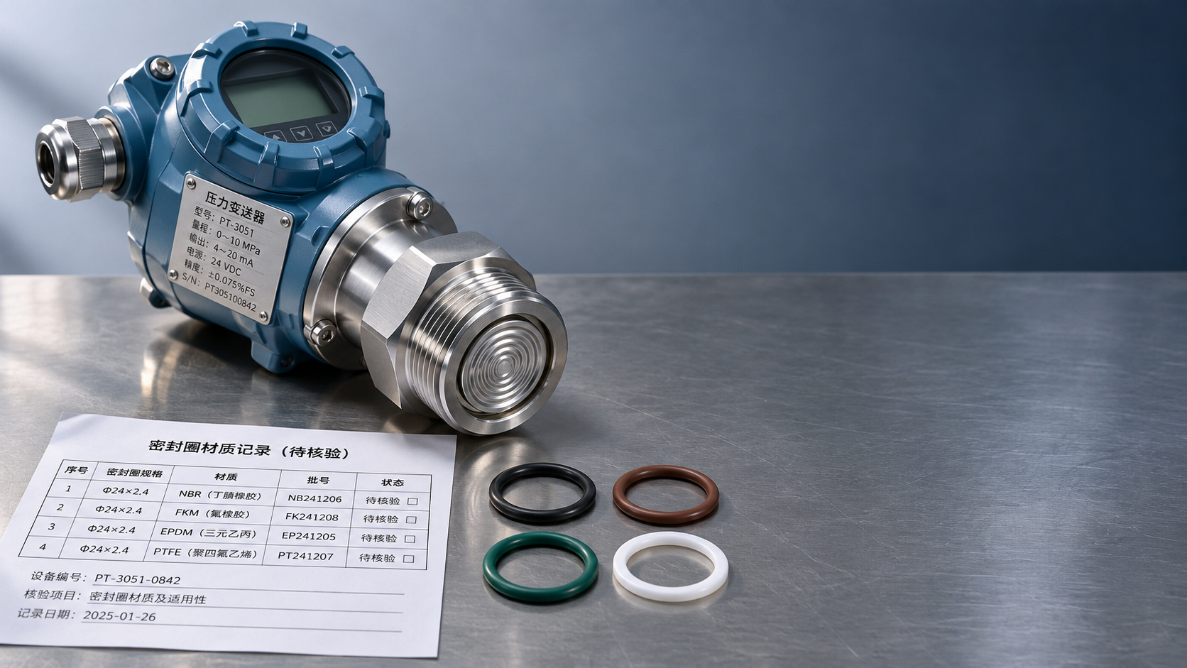
Acceptance records should include the product model, serial number, measuring range, accuracy, output method, supply voltage, process connection, wetted material, and test date. Using data such as 0–10 kPa, 24 VDC, and 4–20 mA as examples, actual test results should be clearly recorded rather than merely stating “qualified.”
For prototypes installed on a trial basis at the customer site, information such as installation location, pressure lead pipe routing, valve manifold status, zero check value, and operating period should be added. It is recommended to recheck the output after 24 to 72 hours of continuous operation to determine whether issues such as zero shift, condensate accumulation, or signal fluctuations have occurred.
If deviations are identified, first determine whether they are caused by the transmitter itself, the power supply circuit, wiring shielding, pressure lead piping, or process fluctuations, and then decide whether to modify the measuring range, damping time, installation method, or structural solution. Locating issues through data can avoid unnecessary rework.
V. Prototype Acceptance and Batch Delivery: Establish Replicable Customization Standards
Use Acceptance Conclusions as the Basis for Batch Production
After prototype acceptance is approved, the final confirmed model code, structural drawings, parameter table, inspection requirements, and packaging identification should be formalized as the basis for batch production. Especially when the same project is delivered in batches, it is essential to ensure that the measuring range, connection orientation, output definition, and calibration standards of subsequent products remain consistent with the prototype.
Factory documentation may include product instructions, wiring diagrams, inspection records, certificates of conformity, and installation precautions according to project requirements. For on-site maintenance personnel, clear zero adjustment methods, valve manifold commissioning sequences, and troubleshooting recommendations can shorten commissioning time and reduce the risk of incorrect operation.
If you are carrying out a differential pressure measurement retrofit or have non-standard supporting requirements, you may compile the existing operating condition parameters, connection photos, measuring range requirements, and control system information, and contact the technical personnel of Xi'an Shenghongchuang Instrumentation Co., Ltd. to complete targeted technical confirmation before proceeding with the prototype solution and acceptance plan.
Related Recommendations
 How should mounting connections and safety margins be determined for a high-pressure transmitter used in ultra-high-pressure equipment?
 How an Oil-Filled Pressure Transmitter Works: Pressure Transfer Through the Isolation Diaphragm and Fill Fluid
 Ceramic-Core vs. Oil-Filled Pressure Transmitters: How to Choose Based on Corrosion Resistance and Overload Capacity
 How should the wetted parts of a 316L pressure transmitter be inspected for corrosive media?