News Center
—— NEWS CENTER ——
Xi'an Shenghongchuang Instrument Co., Ltd.
Contact: Mr. Zhang
Mobile: 15529283736
Email: shc-sensor@qq.com
Address: Fortune Building, Sanqiao Street, Xixian New Area, Xi'an, Shaanxi Province
Adjustable Pressure Transmitter Range Setting Methods and Key Field Application Considerations
Adjustable pressure transmitters modify the measuring range through buttons, DIP switches, communication software, or handheld communicators, enabling them to accommodate equipment retrofits, process adjustments, and monitoring requirements under multiple operating conditions. Correct range setting is not determined solely by the upper pressure limit; medium characteristics, peak pressure, control accuracy, output signal, and the range of downstream instruments should also be considered to avoid “small-range overload” or “large-range inaccuracy.”
For pressure transmitters with the commonly used 4~20mA output in industrial applications, 4mA typically corresponds to the lower range limit, while 20mA corresponds to the upper range limit. Taking a range of 0~1.0MPa as an example, the theoretical output at 0.50MPa is 12mA; if adjusted to 0~1.6MPa, the corresponding output at 0.50MPa becomes approximately 9mA. The PLC, digital display meter, and alarm logic should be checked accordingly.
Shaanxi Qinkong Sensor Technology Co., Ltd. can provide standardized and custom measurement and control products for pressure, level, differential pressure, and supporting intelligent digital display control requirements. Before setting the range, confirm the on-site nameplate parameters, power supply method, output type, and wetted material to avoid exceeding the allowable adjustment range without confirming equipment capability.
I. Operating Parameters to Confirm Before Setting the Range
Determine Normal Pressure, Peak Pressure, and Allowable Overload
First, record the system's normal operating pressure, startup transient pressure, shutdown back pressure, and safety valve opening pressure. Normal pressure is recommended to be within 30%~80% of the transmitter's full range, which both provides sufficient fluctuation margin and helps achieve stable resolution.
If the pipeline is subject to pump start/stop operation, water hammer, compressor pulsation, or rapid valve switching, transient peaks may be significantly higher than normal readings. The upper range limit should cover such peaks and be evaluated in conjunction with the product's allowable overload capacity; allowable overload is not a long-term operating range and cannot replace normal selection margin.
For example, if the system's stable pressure is 0.60MPa and the short-term peak is 0.95MPa, a 0~1.0MPa transmitter can provide readings but offers limited margin. If fluctuations are frequent, a 0~1.6MPa range may be prioritized, and the engineering units should be recalibrated in the control system.
Check the Medium, Temperature, and Installation Location
A correct range does not necessarily guarantee reliable measurement. Corrosive liquids, high-viscosity media, crystallizing media, or high-temperature steam may cause pressure ports to clog, diaphragms to be damaged, or temperature drift to increase. Suitable solutions, such as diffused silicon, ceramic, or capacitive types, should be selected according to the medium, and wetted-part requirements for 316L, stainless steel, or special corrosion-resistant materials should be confirmed.
The installation point should avoid strong vibration, thermal radiation, and electromagnetic interference sources whenever possible. When measuring high-temperature media, a condensate bend, cooling tube, or remote seal structure may be used to keep the sensor's actual operating temperature within the allowable range; exceeding the temperature limit may cause zero drift, which cannot be fundamentally resolved even by readjusting the range.
For level applications converted from pressure, changes in medium density and installation height must also be considered. For every additional approximately 10m of water column, pressure increases by approximately 0.098MPa; if medium density changes with temperature or concentration, the level display ratio should be corrected based on actual density.
II. Steps for Setting the Range of an Adjustable Pressure Transmitter
Operate in the Sequence of “Lower Limit, Upper Limit, Verification”
Before operation, isolate interlock controls that may cause unintended actions and confirm that the site is in a safe condition. Use a standard pressure source, pressure calibrator, or verified pressure gauge as a reference, check fitting tightness, and drain air bubbles, condensate, or residual medium from the impulse line.
First, set the LRV, namely the lower range value, under zero-pressure or known lower-limit pressure conditions; then apply the target full-range pressure and set the URV, namely the upper range value. Some smart transmitters support direct engineering-unit setting through buttons, while zero, span, and damping adjustments can also be completed through RS485 communication parameters.
After setting is complete, verification should be performed at no fewer than five test points: 0%, 25%, 50%, 75%, and 100%. If the allowable error is ±0.5%FS, the corresponding error at a 1.0MPa full range is approximately ±0.005MPa; during testing, verify whether the output current, displayed value, and control system acquisition value are consistent.
4~20mA Signal Conversion Reference
The calculation formula for linear output is: output current=4mA+16mA×(current pressure-lower range limit)÷(upper range limit-lower range limit). This formula can be used to check whether the current measured by the PLC analog input module, digital display control instrument, and on-site multimeter is reasonable.
For example, if the range is -0.10~0.90MPa and the current pressure is 0.40MPa, the pressure span is 1.00MPa and the current position is 50% of the range, with a theoretical output of 12mA. A compound range with negative pressure cannot be assessed by treating 0MPa as 4mA; the specified lower limit must be used as the reference.
If 0~10V output is used on site, the input impedance and common-ground method at the receiving end must also be confirmed. Long-distance voltage signals are more susceptible to line voltage drop and interference; transmission distances exceeding several tens of meters are generally better suited to 4~20mA or communication solutions with isolation functions.
III. Coordinated Settings for Alarm Thresholds and Relay Outputs
Alarm Values Should Avoid the Normal Fluctuation Range
Pressure transmitters with local display and relay outputs can directly set high alarms, low alarms, hysteresis, and delay. The high alarm value should not be set too close to the normal maximum pressure, nor should the low alarm value be set too close to the normal minimum pressure; otherwise, minor equipment fluctuations may cause frequent alarms or repeated relay actuation.
For example, if equipment pressure normally varies between 0.45~0.55MPa, the high alarm can be set to 0.65MPa and the low alarm to 0.35MPa, with hysteresis set to 0.03~0.05MPa. Hysteresis allows the alarm to be cleared after pressure recovery, reducing contact chatter and the probability of false alarms.
Before wiring relay outputs, verify contact capacity, normally open or normally closed logic, load voltage, and whether an intermediate relay is required. For inductive loads such as motors and solenoid valves, driving through a contactor or intermediate relay is recommended, with a suppression circuit installed to prevent reverse voltage from affecting instrument stability.
IV. Troubleshooting Inaccurate Readings and Abnormal Remote Transmission Signals
First Distinguish Between Sensor Error, Installation Error, and System Error
When the reading of an on-site display pressure transmitter is abnormal, first compare it with a standard gauge at the same pressure tapping point. If the deviation between the standard gauge and transmitter is fixed, check the zero, span, and range parameters; if the deviation increases as pressure changes, further assessment is needed for nonlinearity, blockage, diaphragm damage, or receiving-end conversion errors.
Remote 4~20mA signal attenuation is often related to insufficient supply voltage, excessive line resistance, terminal oxidation, improper shield grounding, or multipoint common grounding. Measure the actual supply voltage and loop current at the transmitter terminals, check whether the shield is normally grounded at one end only, and route power cables separately from signal cables.
Local-display pressure transmitters with IP65, IP67, or higher protection ratings must still be evaluated in combination with the installation environment. In outdoor rain exposure, washdown areas, and high-humidity environments, pay particular attention to cable connectors, sealing rings, and the tightness of the meter cover; after waterproof protection fails, moisture entering the terminal chamber may cause display fluctuations, communication interruption, or output drift.
V. Recommendations for Selecting Wired, Wireless, and Electronic Solutions
Electronic pressure transmitters can provide continuous signals, remote transmission, display setting, and alarm control, making them suitable for automated production lines, energy pipeline networks, and equipment interlock applications; mechanical pressure gauges have an intuitive structure and require no power supply, making them suitable for rough local observation. When PLC control or data traceability is required, electronic solutions offer more evident application value.
Wired pressure transmitters offer greater advantages in locations with stable power supply, high real-time requirements, and suitable wiring conditions. Wireless pressure transmitters are suitable for difficult-to-wire locations, mobile equipment, or dispersed-point retrofits, but signal coverage, acquisition cycle, battery capacity, and on-site temperature should be evaluated; battery life is affected by reporting frequency, wireless distance, and low-temperature environments and cannot be judged solely by the rated service life.
When purchasing, domestic or imported origin should not be used as the sole criterion. Focus should be placed on comparing range coverage, accuracy class, temperature adaptability, wetted materials, response time, certification documents, delivery time, and after-sales calibration capability. For non-standard interfaces, special media, or complex control logic, prioritize manufacturing service systems capable of providing operating-condition confirmation and technical support.
Before adjusting the pressure transmitter range, organize parameters such as normal pressure, peak pressure, medium temperature, installation interface, power supply and output, and control requirements. Have professional technical personnel complete selection verification, range setting, and five-point calibration to ensure that measurement data genuinely supports safe and stable equipment operation.
Related Recommendations
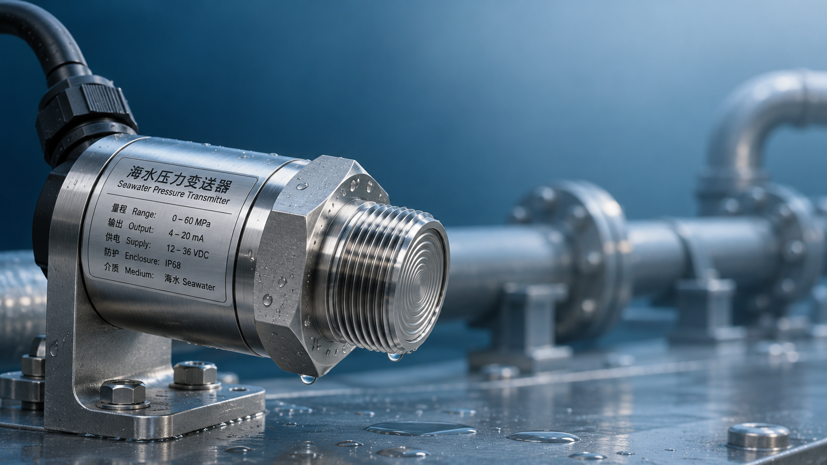
 How to Choose Wetted Materials for Seawater Pressure Transmitters: Titanium Alloy vs. Stainless Steel Corrosion Resistance
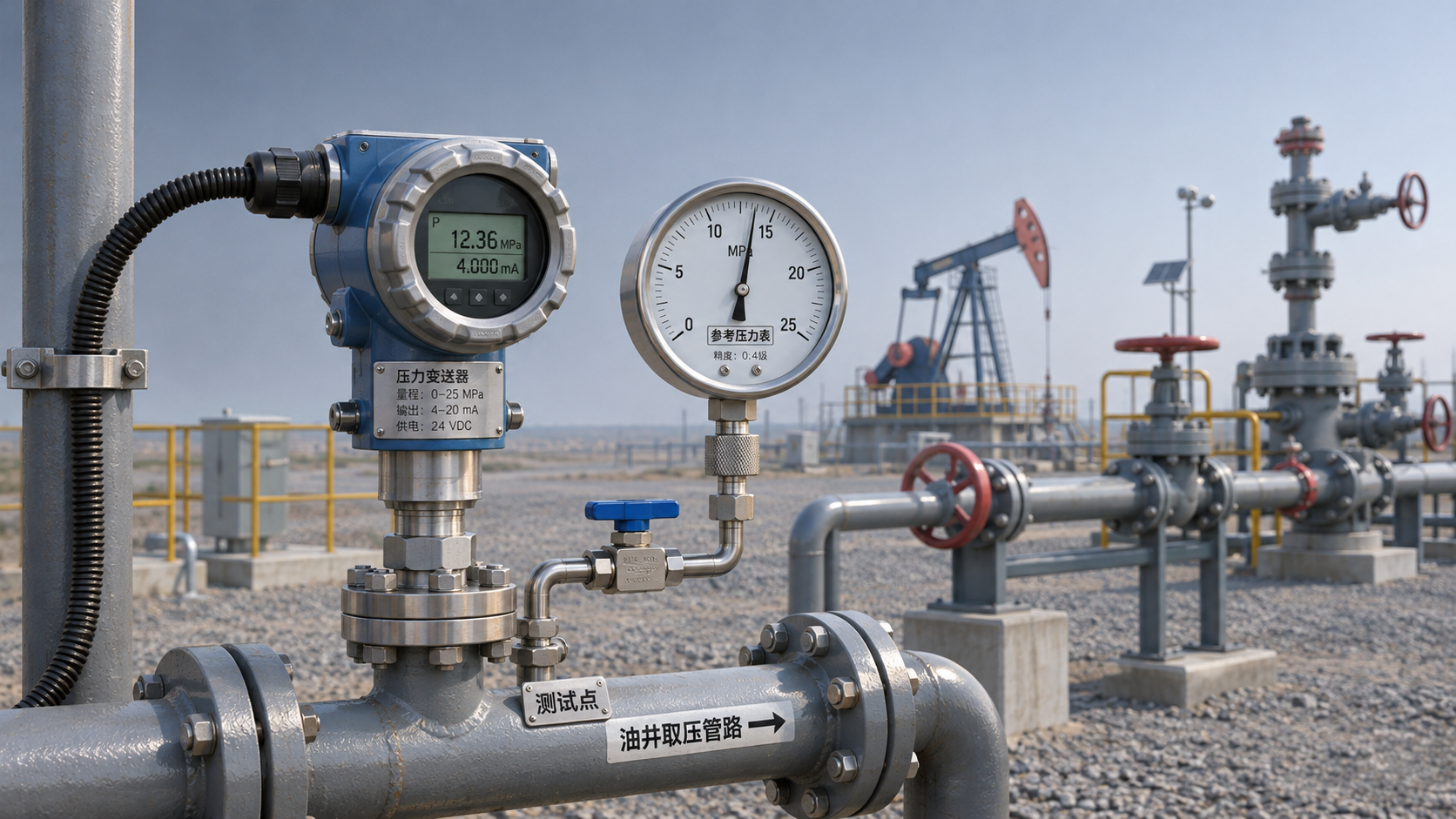
 Common Causes of Reading Drift in Oil Well Pressure Transmitters and On-Site Troubleshooting Methods
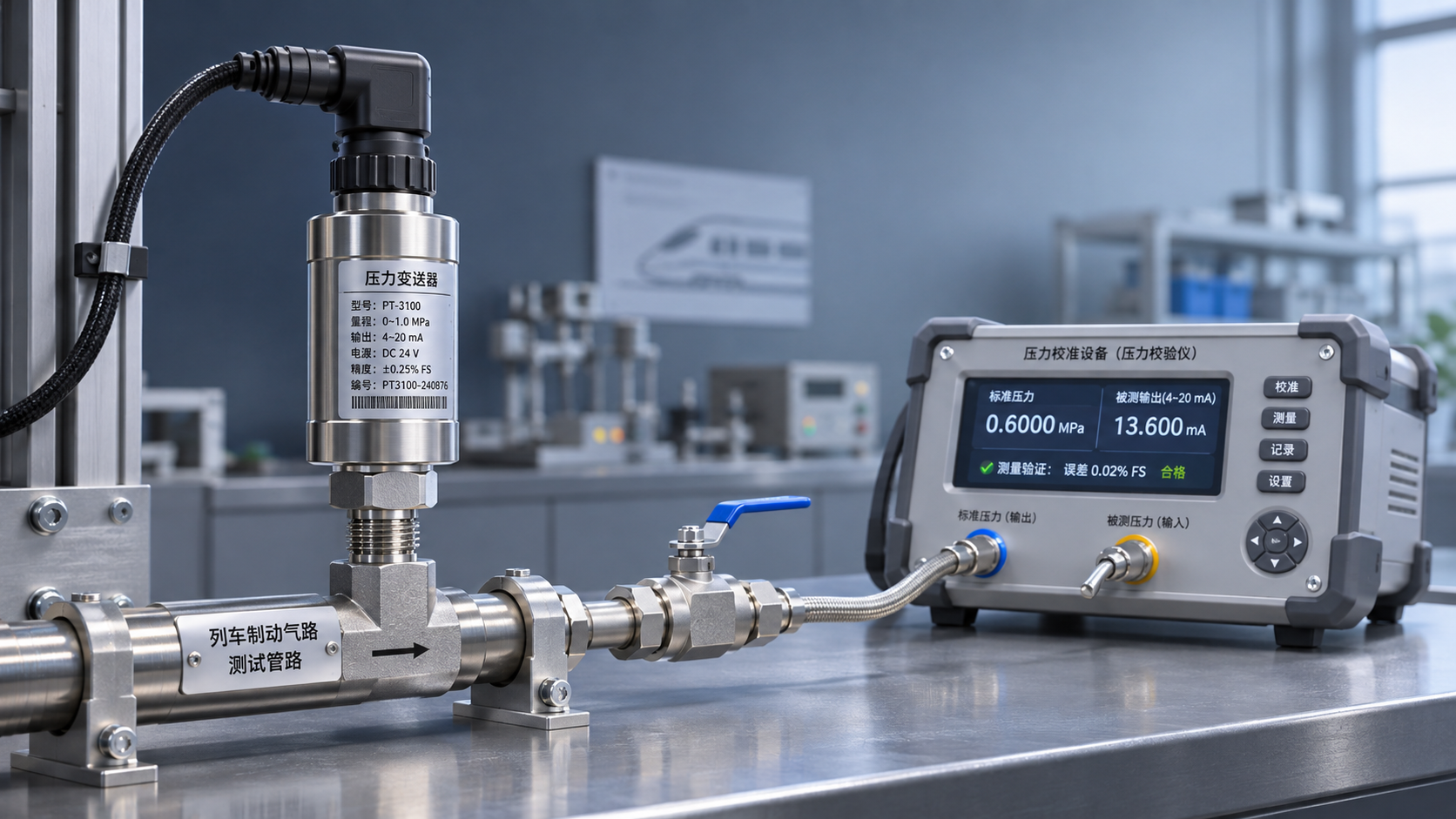
 What validation items should be considered when using railway pressure transmitters in train braking systems?
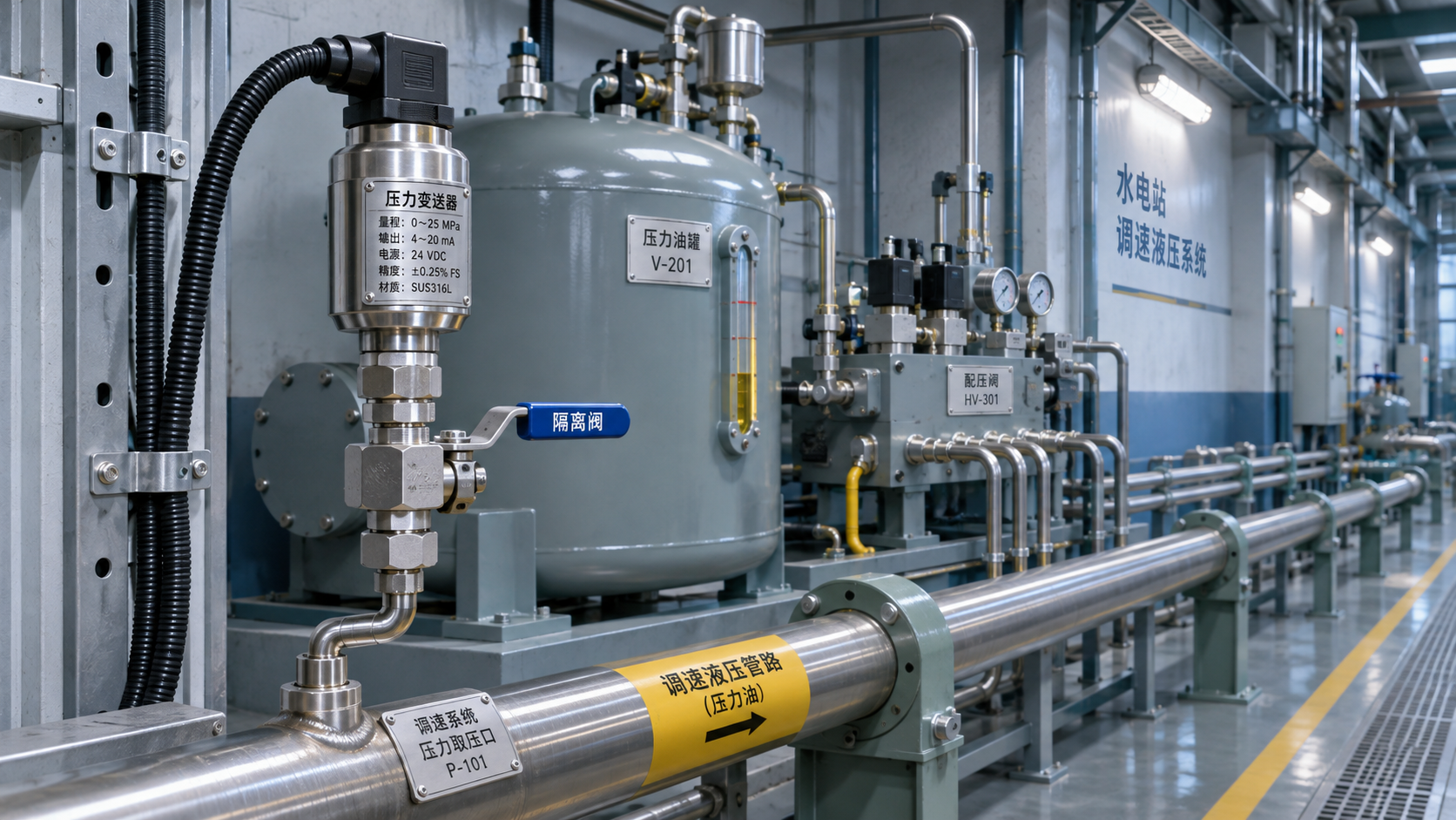
 Measuring Point and Installation Plan for Hydropower Pressure Transmitters in Turbine Governor Systems