News Center
—— NEWS CENTER ——
Xi'an Shenghongchuang Instrument Co., Ltd.
Contact: Mr. Zhang
Mobile: 15529283736
Email: shc-sensor@qq.com
Address: Fortune Building, Sanqiao Street, Xixian New Area, Xi'an, Shaanxi Province
Drift in oil well pressure transmitter readings can affect field monitoring and decision-making. Troubleshooting should distinguish actual pressure changes from instrument errors by checking process conditions, pressure impulse lines, power and signal circuits, and the sensor itself, rather than blindly zeroing or replacing the equipment.
1. First determine whether the readings are actually drifting
Compare operating conditions with historical records
A gradual change in pressure readings does not necessarily indicate a transmitter fault. Oil well start-ups and shutdowns, changes to injection and production schedules, valve position changes, and changes in medium temperature can all cause actual pressure fluctuations. First, confirm recent operations and production conditions with field process personnel.
Retrieve trend records and check whether the deviation is accumulating continuously in one direction or changing periodically with temperature or equipment start-up and shutdown cycles. Also record the transmitter tag, range, pressure type, medium temperature, and when the abnormality was first detected to provide a basis for subsequent comparison.
Verify using a reference instrument
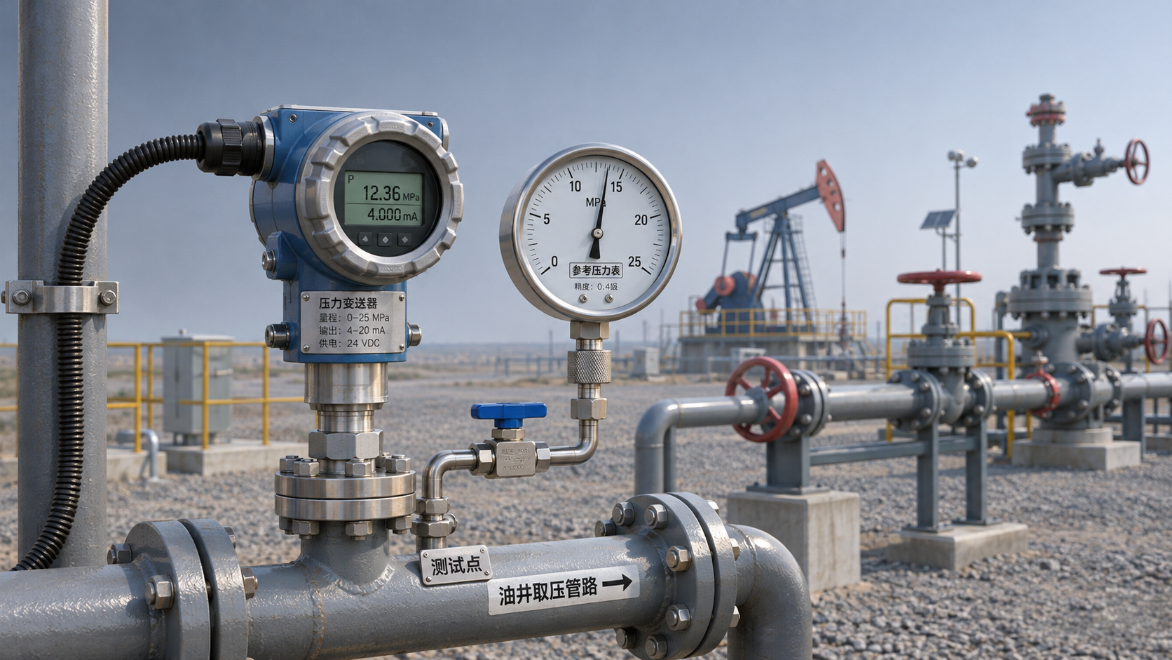
Subject to applicable field safety requirements, connect a verified or calibrated reference pressure instrument suitable for the operating conditions to the designated test point. Before comparing readings, confirm that both instruments have the same measurement location, pressure reference, and units. Also account for differences in the elevation of pressure tapping points and pressure drop caused by flow in the lines.
Observe several pressure points under stable conditions, such as 20%, 50%, and 80% of the range. Record the difference between the reference and displayed values. If the deviation is approximately constant, focus on checking the zero point; if it increases as pressure rises, further check the range settings and sensor performance.
2. Common causes of drift and their field symptoms
Analyze process-side and instrument-side factors separately
Oil well media may contain sand, wax, corrosive components, or other impurities. Over time, the pressure tapping channel may become blocked, or the isolating diaphragm may become fouled or damaged. These issues commonly appear as a slow response, delayed reading recovery after pressure decreases, or a trend that does not match that of a reference instrument.
Changes in ambient temperature, vibration, overpressure shocks, and aging electronic components may also affect measurement results. Temperature-related deviations should be assessed against the equipment’s permitted operating temperature and installation environment. A difference between daytime and nighttime readings alone is not enough to conclude that the sensor is damaged.
Unstable power, loose terminals, water ingress into cables, and electromagnetic interference may cause signal fluctuations or shifts. If the local measurement is normal but the control system display is abnormal, check the signal loop, input channel, and engineering-unit scaling first.
3. Field troubleshooting steps
Check external conditions first, then inspect the instrument
First, inspect the installation location, connections, valve manifold, and cables for signs of leakage, mechanical damage, water accumulation, or abnormal vibration. Do not loosen connections under pressure or remove the transmitter to inspect the diaphragm.
Second, check the pressure tapping path. Qualified personnel must follow the site work permit, isolation, and depressurization procedures to confirm effective isolation and verify that pressure has been released before checking for blockages or deposits. At well sites handling toxic or flammable media such as hydrogen sulfide, gas detection and the relevant protective measures are also required.
Third, check the electrical loop. When work is permitted, measure the voltage at the transmitter terminals and the loop current, and compare them with the equipment manual requirements. Instruments used in hazardous areas, their wiring, and maintenance work must comply with site explosion-protection requirements.
Check the signal and system display
For a transmitter configured with a linear 4–20 mA output, check that the current corresponds to the configured range while pressure is stable. For example, with a range of 0–10 MPa, 5 MPa should theoretically correspond to 12 mA. Actual assessment should also account for instrument error, output configuration, and the field load.
If the transmitter output matches the reference pressure but the system display does not, check the acquisition channel’s range limits, units, signal type, and configuration. If the terminal output itself is abnormal, continue checking the power supply, wiring, and transmitter calibration status.
4. Calibration, corrective action, and return to service
Select corrective action based on the inspection results
After completing the external checks, if a transmitter deviation is still suspected, calibrate it in accordance with the equipment manual and site procedures. Before calibration, confirm that the reference instrument is suitable for the application and within its valid calibration period, and record the pre-adjustment data. Before zeroing or adjusting the range, verify that the actual pressure conditions meet the requirements.
Do not treat a reading taken under pressure as the zero point, and do not use zeroing to mask damage caused by blockage, leakage, or overpressure. If multipoint calibration results exceed the permitted error, or there is obvious hysteresis or abnormal repeatability, further repair or replacement is required.
During reinstallation, verify the pressure rating, process connection, media compatibility, and condition of the seals. After returning the equipment to service, check the connections for leaks and monitor the readings against a reference instrument or reliable operating data. Also retain records of the fault cause, corrective actions, and verification results.
5. Maintenance boundaries for related measurement equipment
Select pressure and weighing instruments for their respective applications
Oil well sites and associated production systems may use both pressure transmitters and load cells, but they measure different things: a pressure transmitter measures the pressure of a medium, while a load cell converts changes in applied force into an electrical signal. They are not interchangeable.
For weighing applications such as batching hoppers or aggregate scales, the Chinese-Made CZL-3 Column-Type Tension Load Cell for Batching Hoppers and Aggregate Scales may be considered based on the actual loading configuration and installation conditions. The listed range for this series is 5 kg–20 t, and it supports tension and compression measurement. Confirm specific specifications and installation requirements with the supplier.
Xi'an Shenghongchuang Instrumentation Co., Ltd. provides sales and technical services for sensors, transmitters, and related instruments. If oil well pressure readings continue to drift, compile the equipment model, range, medium, abnormal trend, and field calibration data, and contact technical personnel to jointly confirm a troubleshooting and selection plan.
Related Recommendations
 How to Choose Wetted Materials for Seawater Pressure Transmitters: Titanium Alloy vs. Stainless Steel Corrosion Resistance
 Common Causes of Reading Drift in Oil Well Pressure Transmitters and On-Site Troubleshooting Methods
 What validation items should be considered when using railway pressure transmitters in train braking systems?
 Measuring Point and Installation Plan for Hydropower Pressure Transmitters in Turbine Governor Systems