News Center
—— NEWS CENTER ——
Xi'an Shenghongchuang Instrument Co., Ltd.
Contact: Mr. Zhang
Mobile: 15529283736
Email: shc-sensor@qq.com
Address: Fortune Building, Sanqiao Street, Xixian New Area, Xi'an, Shaanxi Province
The measurement points and installation plan for hydraulic pressure transmitters directly affect the monitoring reliability of a hydro turbine governing system. This article outlines key selection and installation considerations for project managers.
1. First, determine what the governing system needs to monitor
Determine measurement points based on control functions
A hydro turbine governing system maintains stable unit speed and output by adjusting the guide vane or injector needle opening. Pressure signals can be used to monitor the hydraulic oil supply and may also support alarms, interlocks, or operating trend analysis. However, the control logic varies among units.
Before establishing measurement points, review the governor schematic, hydraulic system diagram, and protection setpoint table to distinguish signals used for continuous regulation, status monitoring, and protective actions. For critical functions such as shutdown and emergency pressure distribution, consider independent measurement, redundancy, and fault diagnosis as required by the design.
Assess pressure signals alongside equipment status
The same pressure reading may correspond to different conditions, such as normal pressure holding, oil pump startup, or actuator movement. During commissioning, check oil pump start/stop status, servomotor stroke, and valve position at the same time to avoid interpreting pressure changes in isolation.
For retrofits of older units, also confirm how the existing pressure switches and mechanical gauges relate to the new transmitters. Do not replace existing protective elements with new instruments without proper assessment or make arbitrary changes to protection circuits already in service.
2. Key measurement points and installation locations
Measurement points for the oil pressure unit and actuators
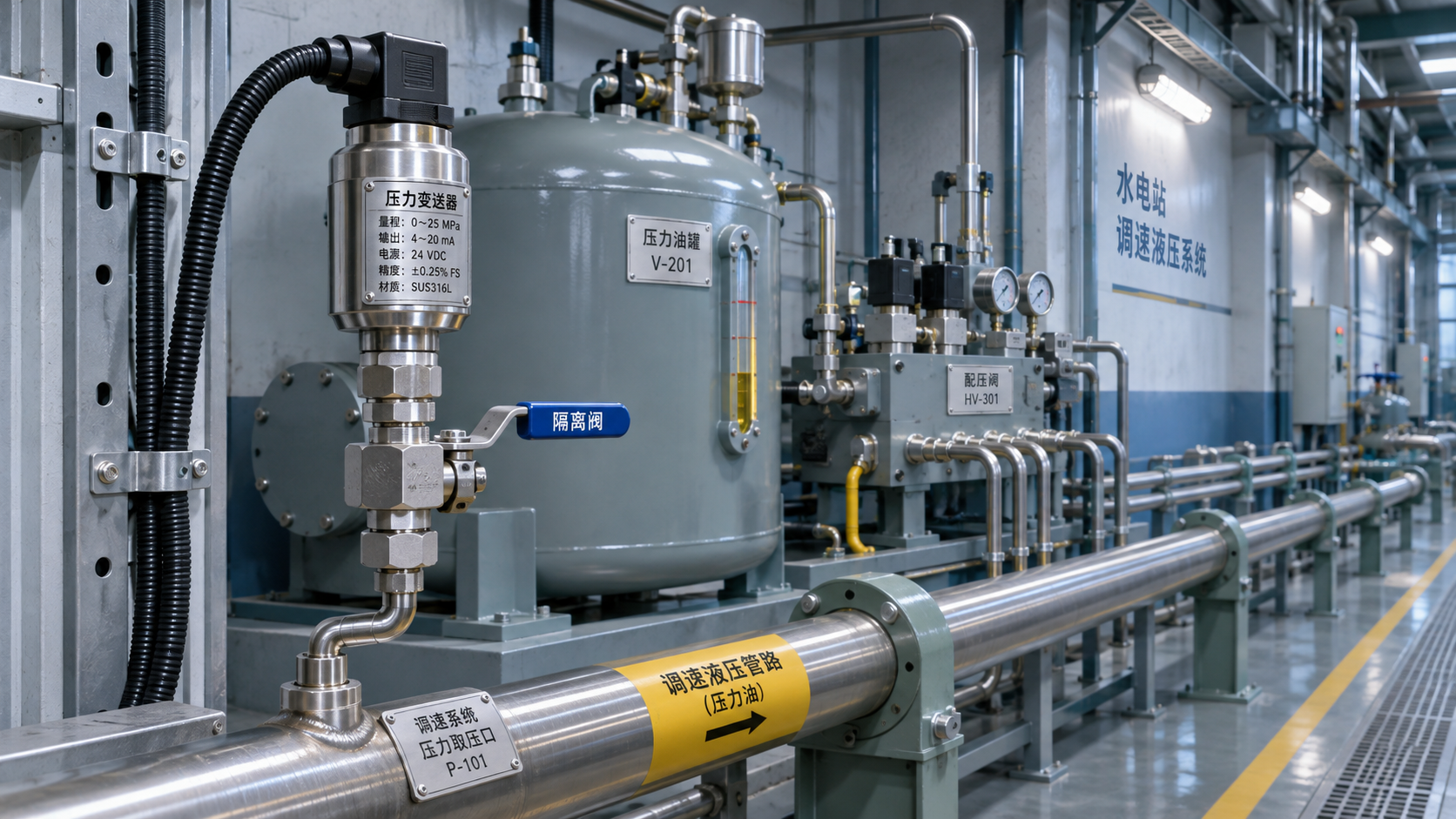
The outlet of the pressure oil tank or accumulator is an important location for monitoring the status of the governing oil supply. It can track changes in operating pressure and provide a basis for oil pump start/stop control and low oil pressure alarms. The specific pressure tap location should be determined based on the arrangement of the accumulator, check valve, and isolation valve.
The supply side of the main pressure distributing valve indicates the oil supply pressure entering the control circuit. A measurement point in the servomotor working chamber helps analyze pressure changes during operation. The latter should generally be assessed alongside the pressure in the opening and closing chambers and displacement signals; actuator performance should not be judged based on pressure on one side alone.
Set up auxiliary measurement points as needed
Return line pressure can be used to monitor return backpressure, while the pressure differential across a filter can help identify trends in filter element clogging. The differential pressure alarm value should be determined according to the filter manufacturer's specifications and the site conditions for oil temperature and flow rate; values from other units should not be applied directly.
If the project requires monitoring the pressure of water for water guide bearing cooling, seal water, or other water systems, separately verify water quality, operating temperature, water hammer, and protection requirements. These measurement points involve a different medium from the governing oil pressure system and cannot simply use the same selection criteria.
3. Transmitter selection and application limits
Match range, accuracy, and response to operating conditions
When selecting a range, consider normal operating pressure, peak pressure during startup and shutdown, allowable overpressure, and system pressure rating. For a measurement point with a normal pressure of approximately 4 MPa, for example, whether to use a 0–6 MPa range must be confirmed by the design engineer based on actual pressure peaks and protection requirements.
Accuracy is usually expressed as a percentage of full scale. For example, an instrument with a 0–6 MPa range and an overall accuracy of ±0.25% FS has a full-scale accuracy limit of approximately ±0.015 MPa. Factors such as temperature drift, installation, and calibration must also be included in the assessment of actual measurement error.
Distinguish gas differential pressure from hydraulic pressure measurement
Governing system projects may also involve monitoring gas pressure differentials in cabinet or equipment ventilation. FST800-901 Domestic Differential Pressure Transmitter: Low-Range Gas Differential Pressure Transmitter for Wind Pressure Measurement is suitable for dry, non-corrosive, dust-free gases. Outputs such as 4–20 mA are available; the specific range and connection should be confirmed in the order.
The product's media compatibility does not include governing hydraulic oil or water, so it should not be used directly for oil pressure, servomotor working chamber, or water system measurements. Differential pressure measurement points for liquid filters should also use instruments explicitly rated for liquids and meeting the requirements for single-sided static pressure and overpressure.
4. Installation, commissioning, and acceptance
Pressure connections and cable routing
Where possible, use equipment-provided pressure ports and install an isolation valve rated for the system pressure and medium to facilitate maintenance. The fitting thread, sealing method, and pressure rating must match the site connection. Do not use excessive tightening to compensate for mismatched specifications.
For locations subject to significant vibration or pressure fluctuations, suitable supports, impulse tubing, or damping measures may be used after design approval. Also assess the impact of damping on response time. Impulse tubing must be securely fixed to prevent trapped air, mechanical stress, and external impact.
Complete circuit checks before commissioning
Signal cables should preferably be routed separately from power cables. Shielding and grounding must follow the equipment manufacturer's instructions and the power station's design requirements. For a circuit with a 24 VDC power supply and 4–20 mA output, for example, verify the supply voltage, wiring polarity, load capacity, and control system range settings.
Before commissioning, qualified personnel must supervise isolation, depressurization, calibration, and sealing checks, and verify the zero point, range, alarm values, and signal direction. Disassembly or installation under pressure and modifications to protection circuits must follow the power station's work permit and safety procedures. Interlock testing must be carried out according to an approved plan.
5. Project handover and ongoing maintenance
Maintain traceable measurement point records
Handover documents should record the measurement point ID, installation location, pressure type, range, output signal, calibration results, and associated control channel to ensure that site labels match the drawings. For critical measurement points, also retain records of alarm and interlock tests.
During operation, inspect fitting leaks, cable protection, and zero-point drift in line with maintenance intervals. Analyze pressure trends together with oil pump start/stop frequency and actuator operation records. Set calibration intervals according to equipment requirements, site conditions, and management procedures.
Information checklist before submitting a selection request
Before purchasing or retrofitting, prepare the system diagram, measurement medium, normal and maximum pressures, process connection, power supply, and output requirements. If the measurement point serves a protection function, also provide redundancy and fail-safe requirements.
Project managers can submit the above information to Xi'an Shenghongchuang Instrumentation Co., Ltd. for review of the transmitter model, installation connection, and supporting solution against the specific operating conditions, and then confirm implementation requirements jointly with the unit's design and operations teams.
Related Recommendations
 What validation items should be considered when using railway pressure transmitters in train braking systems?
 Measuring Point and Installation Plan for Hydropower Pressure Transmitters in Turbine Governor Systems
 What Can Hydraulic Pressure Transmitters Measure? Applications from Reservoir Water Levels to Pipeline Pressure
 Connecting an RS232 Pressure Transmitter to a Host Computer: Serial Port Parameters and Communication Troubleshooting