News Center
—— NEWS CENTER ——
Xi'an Shenghongchuang Instrument Co., Ltd.
Contact: Mr. Zhang
Mobile: 15529283736
Email: shc-sensor@qq.com
Address: Fortune Building, Sanqiao Street, Xixian New Area, Xi'an, Shaanxi Province
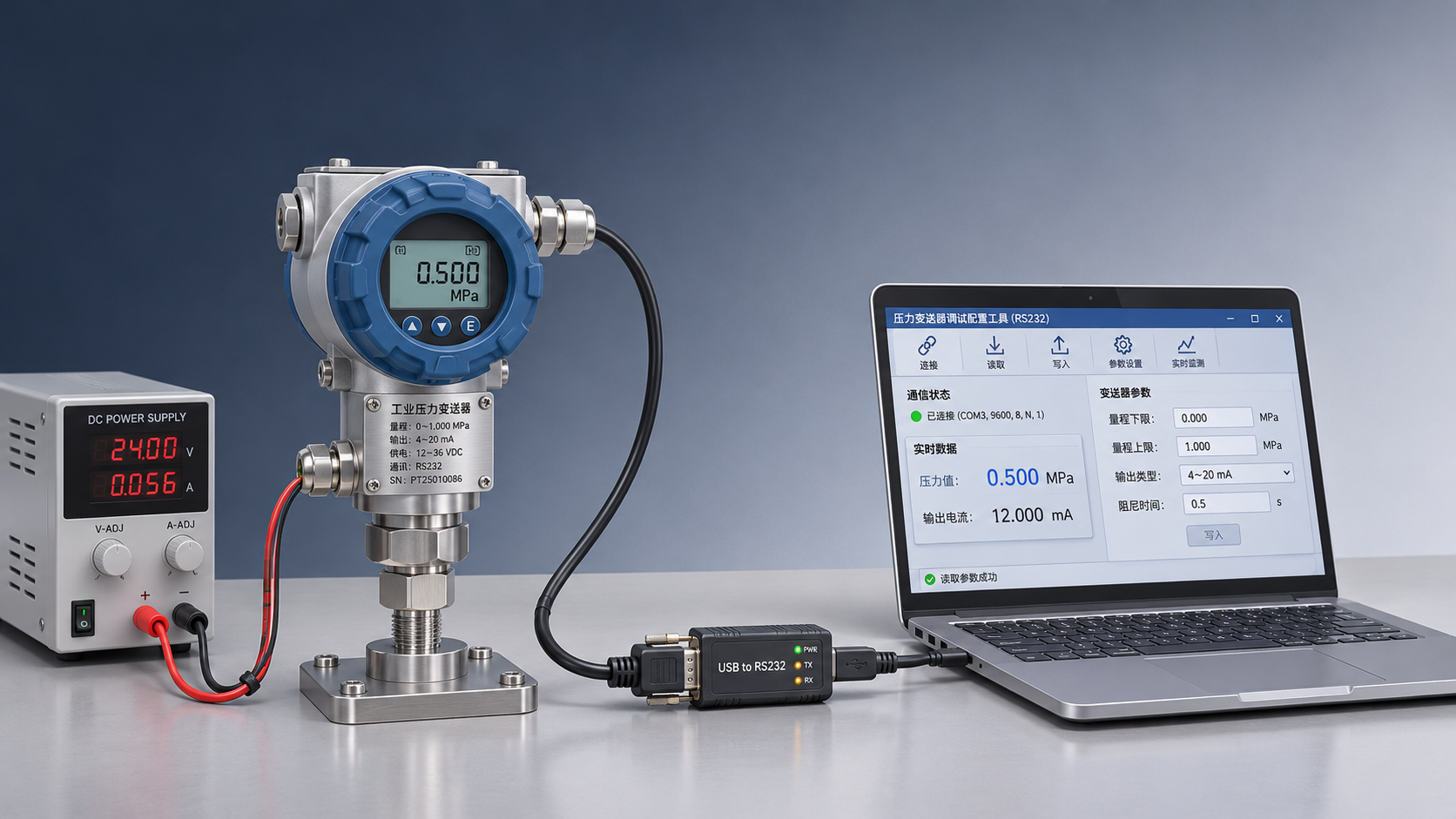
When connecting an RS232 pressure transmitter to a host computer, mismatched serial port parameters or incorrect wiring may cause communication failure. Understanding parameter setup and debugging methods helps quickly identify the problem.
I. Verify the interface and power supply before connection
First, distinguish the communication interface from the output signal
RS232 is a serial electrical interface that specifies signal levels and interface characteristics; it is not a communication protocol. Before wiring, check the transmitter nameplate, wiring diagram, and communication manual to confirm that the device actually has an RS232 interface and whether it uses active data transmission or host polling.
A pressure transmitter may also output a 4~20mA current or a 0~10V voltage. These analog signals cannot be connected directly to an RS232 port. They must first be connected to a compatible data acquisition module, which then sends the data to the host computer through a module with serial communication capability.
For example, Domestic Industrial 2088 Pressure Transmitter YL-BP800 Diffused Silicon 2088 Pressure Sensor offers analog output options such as 4~20mA, 0~5V, and 0~10V. Refer to the ordered configuration for details. To read data via RS232, use a data acquisition module that matches the output type and supports RS232 communication. Do not connect the analog output terminals directly to the computer's serial port.
Check the power supply and wiring definitions
The transmitter's power supply must comply with the device manual; do not assume that it is powered by the computer's serial port. Before powering on, check the power supply polarity, output terminals, and common terminal, and use a multimeter to confirm that the supply voltage is within the permitted range. Before working on pressure piping, isolate the pressure and release it according to site procedures.
RS232 typically requires connections for transmit (TX), receive (RX), and signal ground (GND). In general, connect the transmitter's TX to the host computer's RX, the transmitter's RX to the host computer's TX, and connect the signal grounds of both devices. The actual pin numbers and wiring sequence must be verified against the documentation for the device and converter.
If the computer does not have a native serial port, use a USB-to-RS232 converter. Choose a product that genuinely conforms to RS232 signal levels, install its driver, and check the port number in Device Manager. TTL serial uses different signal levels from RS232, so the devices must not be connected directly based only on similar-looking connectors.
II. Match the serial port parameters and protocol
Set the basic communication parameters
Open the serial port debugging software and select the COM port assigned to the converter. Then set the baud rate, data bits, parity, and stop bits. Both devices must use the same settings. Configure the flow control as required by the device; if flow control is not used, explicitly disable it in the software.
The combinations in the table below are for debugging purposes only and are not the factory settings for all pressure transmitters. When connecting a device for the first time, consult its manual or confirm the settings with the supplier to avoid spending too long guessing each parameter.
After setting the parameters, close any other software using the COM port. When changing the device's serial port parameters, record both the original and new values. Some devices require the configuration to be saved or the device to be powered on again before the changes take effect. Follow the manual for the specific procedure.
Confirm the data format and reading method
A normal physical connection does not guarantee that pressure values can be decoded. You must also confirm the protocol type, device address, command format, checksum algorithm, response length, and timeout requirements. Some devices use Modbus RTU, while others use manufacturer-specific protocols; their commands are not interchangeable.
For a device using Modbus RTU, identify the slave address, function code, and register address. The register number in the manual may differ by 1 from the address entered in the software. During debugging, check the software's address convention rather than immediately concluding that the device is not responding.
Pressure data may be represented as a signed integer, unsigned integer, or floating-point number, and may also use a scaling factor. For example, if the raw value is 1250 and the scaling factor is 0.001, the calculated result is 1.250. The unit—MPa, kPa, or another unit—must still be confirmed from the protocol definition.
III. Debug communication step by step
Verify each layer, from the port to the data
First, power the transmitter steadily under safe operating conditions and confirm that the COM port opens normally on the computer. If the device uses active data transmission, check the receive window after connection. If it uses polling, send a known valid read command according to the protocol.
Before sending, check whether the software is in text mode or hexadecimal mode. Binary protocols usually require data to be sent byte by byte. If hexadecimal characters are sent as ordinary text, the bytes received by the device will be different, and it may not respond.
After receiving a message, first check the address, length, and checksum, then convert the data according to the register definitions. For 32-bit floating-point values, also verify the word order and byte order of the two 16-bit registers to prevent extremely large values, negative values, or fluctuating readings.
Verify the readings against a pressure source
After communication is established, apply a known pressure within the device's permitted range and compare the host computer reading with that of a reference instrument. Check multiple points, such as zero, a midpoint, and a point near full scale, and confirm that the gauge, absolute, or vacuum pressure specification matches the measured conditions.
For a 0~1 MPa range, for example, readings near 0, 0.5, and 1 MPa can be checked according to site conditions. Before testing, confirm that the reference instrument's accuracy, range, and calibration status meet the test requirements. Do not exceed the rated pressure of the transmitter or piping.
If the serial data is stable but the readings always have a fixed deviation, first check the zero point, unit, and scaling factor. If the deviation increases with pressure, check the range mapping and sensor condition. Adjust the zero point or range according to the product instructions, and keep records of the values before and after adjustment.
IV. Common faults and on-site maintenance
Narrow down the troubleshooting scope based on the symptoms
If there is no response, first check the power supply, port number, and TX, RX, and GND connections, then verify the communication parameters and device address. If the connection uses a data acquisition module, also check the analog input side, the module power supply, and the module's RS232 side separately to avoid confusing problems in the two stages.
If the data is garbled, focus on the baud rate, parity, and display mode. If the message is complete but the value is abnormal, check the register address, data type, word order, and engineering unit. The symptoms and actions below can serve as a reference for on-site troubleshooting.
When variable frequency drives, motors, or long cable runs are present on site, pay attention to electromagnetic interference, grounding, and cable conditions. RS232 communication distance depends on the data rate, cable capacitance, and environment, so reliability cannot be judged using a fixed distance alone. For longer distances or stronger interference, consider isolation converters or other suitable communication solutions.
Keep debugging records for easier future maintenance
After debugging, record the device model, power supply method, wiring definitions, COM port, serial port parameters, protocol version, and read commands. Also save a normal response message and the pressure conversion method to facilitate fault reproduction and device replacement.
Before project handover, also test power cycling, recovery from communication interruptions, and handling of abnormal data. The host computer should distinguish communication timeouts from zero pressure to avoid displaying a communication failure as a normal measurement value. For control interlocks, design failure handling in accordance with system safety requirements.
Before connecting the device, prepare photos of the transmitter nameplate, the wiring diagram, the communication protocol, and the host computer interface requirements. Contact the technical staff of Xi'an Shenghongchuang Instrumentation Co., Ltd. to confirm the output type and data acquisition solution, then complete the wiring and pressure verification according to site conditions.
Related Recommendations
 What Can Hydraulic Pressure Transmitters Measure? Applications from Reservoir Water Levels to Pipeline Pressure
 Connecting an RS232 Pressure Transmitter to a Host Computer: Serial Port Parameters and Communication Troubleshooting
 RS485 Pressure Transmitter Multi-Drop Networking: How to Set the Terminating Resistor and Device Addresses?
 How Does a HART Pressure Transmitter Use an Overlay Signal for Remote Configuration?