News Center
—— NEWS CENTER ——
Xi'an Shenghongchuang Instrument Co., Ltd.
Contact: Mr. Zhang
Mobile: 15529283736
Email: shc-sensor@qq.com
Address: Fortune Building, Sanqiao Street, Xixian New Area, Xi'an, Shaanxi Province
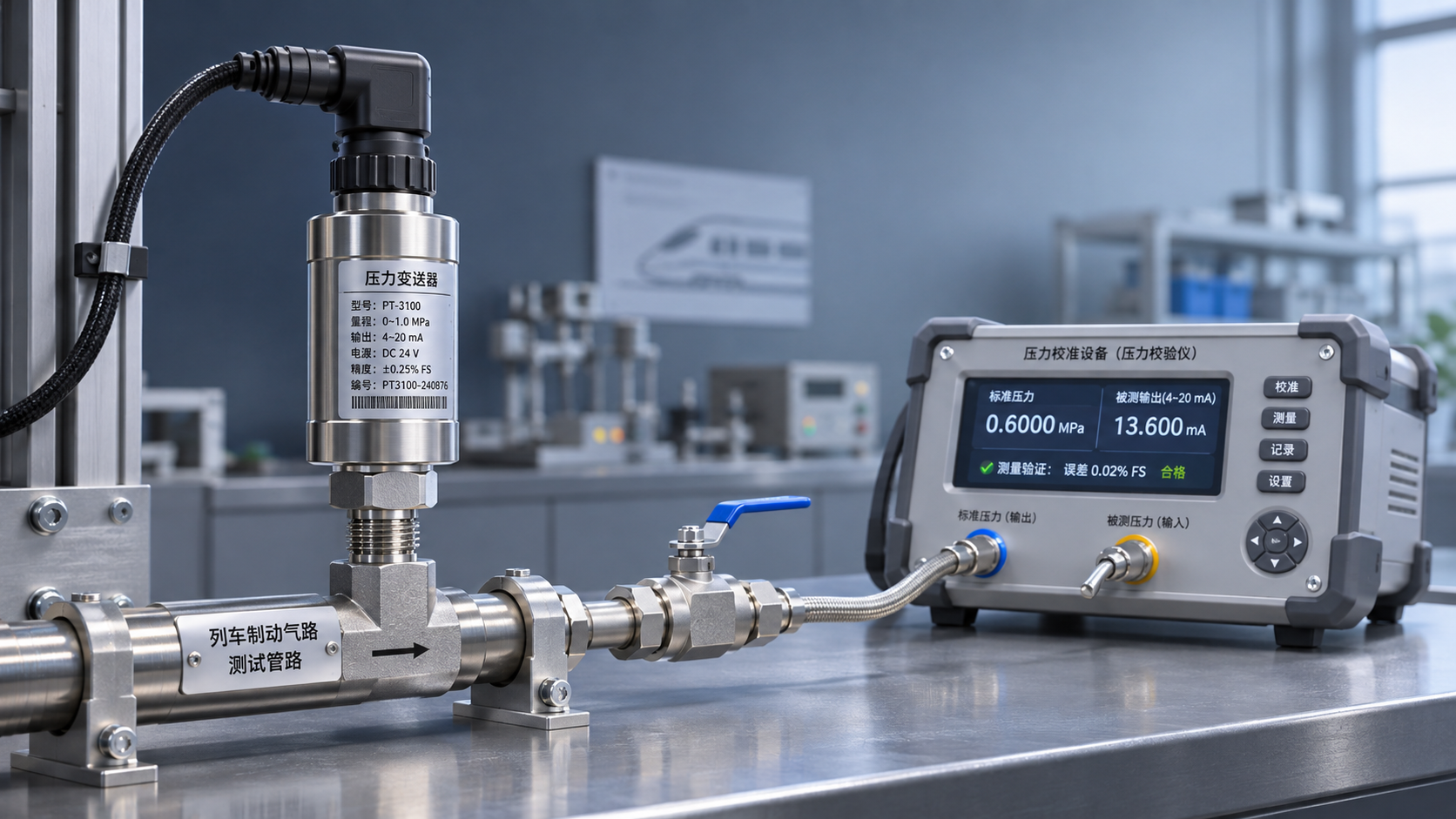
When railway pressure transmitters are used in train braking systems, they must not only measure accurately but also continuously provide reliable signals under vibration, temperature variations, electromagnetic interference, and long-term pressure cycling. For personnel responsible for quality control and safety management, validation should be based on the specific vehicle model, installation location, and brake control strategy, confirming that the device performance, system interfaces, and fault responses meet project requirements.
1. Define the Operating Limits and Acceptance Criteria First
Determine the Validation Scope Based on Braking Conditions
Pressure changes differ at locations such as the brake pipe, main air reservoir, and brake cylinder. Before validation, clarify the measurement medium, normal operating pressure, potential transient peaks, installation space, and expected service life. Selection should not be based solely on the rated range.
The range must cover normal pressure and the specified transient range while also providing adequate resolution in the low-pressure region. For critical pressure points used in braking decisions, verify that the actual error meets the error budget allocated to the transmitter by the system.
The project should also specify the applicable railway product standards, vehicle technical requirements, and test specifications agreed upon by the supplier and purchaser. The applicable standard version and scope should be based on the procurement documents and formal project approvals. General industrial product certification alone cannot replace validation for railway applications.
Validation Input Documents
Before testing, it is recommended to prepare a list of operating conditions covering at least the pressure range, power supply conditions, output interface, environmental rating, installation method, and fault-handling requirements. Each requirement should be linked to a test method and acceptance criterion.
2. Validate Measurement Performance and Pressure Resistance
Static Accuracy and Dynamic Response
Static calibration should cover zero, full scale, and intermediate pressure points, with measurements taken during both increasing and decreasing pressure to check linearity, hysteresis, and repeatability. Test points such as 0%, 25%, 50%, 75%, and 100% of the range may be used; the final points and acceptance limits should be determined according to the project specifications.
In addition to room-temperature calibration, verify changes in zero and sensitivity over the specified temperature range, paying particular attention to whether temperature cycling causes irreversible drift. The reference instruments used for testing should have valid traceability, and their measurement uncertainty should be appropriate for the accuracy requirements of the product under test.
Train braking pressure may change rapidly. Response time, sampling delay, and output update behavior should be checked against actual charging and venting processes. Where necessary, conduct system tests in conjunction with controller filtering and communication cycles to confirm that delays in the signal chain do not lead to misinterpretation of critical pressure changes.
Pressure Resistance, Sealing, and Pressure Cycling
For pressure resistance validation, clearly define the operating pressure, allowable overpressure, and burst pressure, as well as the applicable acceptance methods. After an overpressure test, check for leaks and deformation, and remeasure zero and accuracy. Burst testing should be conducted under the required dedicated protective conditions.
For locations subject to frequent charging and venting, conduct fatigue tests using the specified upper and lower pressure limits, rate of pressure change, and number of cycles. Check sealing performance and output drift before, during, and after testing. Cycling conditions should not simply be copied from those used for other equipment.
For wetted or gas-contacting components, also verify compatibility with compressed air, condensate, oil mist, and cleaning agents. The sealing structure of the connection, tightening torque, and leakage after repeated assembly and disassembly should also be included in validation.
3. Cover Vehicle Environmental Conditions and Electrical Interference
Mechanical, Climatic, and Ingress Protection Tests
During vehicle operation, transmitters are exposed to continuous vibration and shock. Determine test levels according to the installation location, and check whether the housing, connectors, solder joints, and fasteners have loosened or been damaged. During testing, also monitor the signal for interruptions, jumps, or deviations beyond the allowable error.
Risks involving temperature and humidity, condensation, salt spray, rain, and dust vary with the vehicle environment and installation location. When selecting an ingress protection rating, consider the cable outlet, mating connector, and installation orientation as well as the transmitter itself. Do not rely solely on the marking on the sensor body.
After environmental testing, inspect the appearance, insulation, sealing, and measurement performance. Where necessary, conduct combined or sequential tests to identify issues that individual tests may not reveal. Record the condition of the test samples and recovery time in accordance with the project specifications.
Power Supply, Electromagnetic Compatibility, and Interfaces
Electrical validation should cover the power supply range, power-on and power-off processes, and any power fluctuations, interruptions, and surge conditions specified for the project. For a 4–20 mA output, also confirm load capacity, loop power supply requirements, and how abnormal current levels are identified.
Based on the vehicle environment and interface type, electromagnetic compatibility testing should cover applicable items such as electrostatic discharge, electrical fast transients, surges, and radio-frequency interference. Check the output state both during interference and after recovery. Shielding, grounding, and cable harness routing should match the actual vehicle installation design.
Interface validation also includes fault injection for reverse polarity, short circuits, open circuits, and poor contact. Acceptance should consider not only whether the device is damaged, but also whether the control system can promptly detect the fault and carry out the specified alarm or degraded-mode strategy.
4. Implement System Validation and Lifecycle Management
Fault Response and Consistency of Installed Units
Passing performance tests for the pressure transmitter itself does not mean that the braking system has met its safety requirements. Jointly commission the controller, wiring harness, and braking equipment to verify pressure indications, alarms, and control outcomes during normal braking, brake release, and specified fault scenarios.
For faults such as an open circuit, out-of-range signal, or stuck output, check diagnostic coverage and response time. Whether redundancy, cross-checking of signals, or other safety measures are required should be determined by the safety analysis of the vehicle and braking system, not inferred from the specifications of a single device.
After type validation is passed, changes to the sensing element, sealing materials, software version, and critical processes must also be controlled. Establishing batch traceability, outgoing calibration, periodic reinspection, and in-service failure analysis mechanisms helps ensure that validation results remain applicable to products delivered in practice.
Distinguish Pressure Measurement from Other Process Measurements
A pressure transmitter measures pressure in brake piping, while a flowmeter measures the flow rate of a medium in a pipe. They have different measurands and acceptance criteria and cannot replace one another. When selecting a device, first confirm the medium being measured and the purpose of the measurement.
For example, the ZRN-LW-A Chinese-Made Electromagnetic Flowmeter, Inline Intelligent Electromagnetic Flowmeter is designed to measure the volumetric flow of conductive liquids and can be used in relevant industrial liquid pipelines. Its applicable conditions include a medium conductivity greater than 5μS/cm. It is not suitable as a substitute for a pressure transmitter in a train braking air circuit.
During procurement or project reviews, Xi'an Shenghongchuang Instrumentation Co., Ltd. can assist in reviewing interfaces and measurement conditions based on specific requirements. For railway braking applications, however, the project requirements, actual test results, and approvals from relevant parties remain authoritative. It is recommended that the vehicle model, measurement points, pressure range, power supply interface, and environmental conditions be provided so that a traceable, itemized validation checklist can be prepared before selection and testing are arranged.
Related Recommendations
 What validation items should be considered when using railway pressure transmitters in train braking systems?
 Measuring Point and Installation Plan for Hydropower Pressure Transmitters in Turbine Governor Systems
 What Can Hydraulic Pressure Transmitters Measure? Applications from Reservoir Water Levels to Pipeline Pressure
 Connecting an RS232 Pressure Transmitter to a Host Computer: Serial Port Parameters and Communication Troubleshooting