News Center
—— NEWS CENTER ——
Xi'an Shenghongchuang Instrument Co., Ltd.
Contact: Mr. Zhang
Mobile: 15529283736
Email: shc-sensor@qq.com
Address: Fortune Building, Sanqiao Street, Xixian New Area, Xi'an, Shaanxi Province
How to Set the Trigger Threshold for an Alarm Pressure Transmitter: First Define the Warning Objective
The trigger threshold of an alarm pressure transmitter should not simply be set to “close to the upper range limit.” It should be determined comprehensively based on the allowable pressure of the equipment, the normal operating range, the process fluctuation range, and safety interlock requirements. When properly configured, the transmitter can output an alarm signal at the early stage of an abnormality, allowing operators sufficient time to respond. Improper settings may cause frequent false alarms or even eliminate the warning function during actual overpressure events.
Taking a common 0–1.6 MPa electronic pressure transmitter as an example, if the normal operating pressure of the system is 0.85–1.05 MPa, short-term fluctuations can reach 1.12 MPa, and the design allowable pressure of the pipeline is 1.40 MPa, the high alarm point should generally not be set directly at 1.40 MPa. A more prudent approach is to first set a warning value and then configure a high-high alarm or interlock protection value to establish a tiered response.
For pressure transmitters with local display, relay output, or 4–20 mA remote transmission functions, alarm parameters also affect the logic of the control cabinet, audible and visual alarms, and actuator operation. Industrial pressure measurement and control products manufactured by Shaanxi Qinkong Sensor Technology Co., Ltd. can be configured with measuring range, output signal, display method, and alarm control functions according to actual operating conditions, facilitating targeted settings for machinery manufacturing, chemical energy, automated production lines, and other applications.
First Distinguish Between High Alarms, Low Alarms, and Interlock Alarms
A high alarm is used to indicate excessively high pressure and is commonly applied in hydraulic stations, air compressors, water supply pipe networks, reactors, and filtration equipment. When pressure continues to rise but has not yet reached the hazardous range, the system can use a high alarm to prompt inspection of valve opening, pipeline blockage, pump unit condition, or load changes, preventing the abnormality from escalating further.
A low alarm is used to identify issues such as insufficient supply pressure, leakage, pump unit failure, insufficient medium, or filter blockage. For example, if the normal pressure of an air source system is 0.60 MPa and the minimum pressure required to maintain stable equipment operation is 0.48 MPa, the low alarm point can be set at approximately 0.50 MPa rather than waiting until the pressure drops to a level at which the equipment cannot operate.
An interlock alarm is a higher-level protection logic. Once the high-high or low-low alarm point is reached, the system can automatically stop the pump, close the valve, switch to standby equipment, or disconnect related loads. Warning alarms allow manual confirmation and handling, whereas interlock values should provide an adequate safety margin and should not be set too close to ordinary alarm values.
Core Calculation Method for Trigger Threshold Settings
Before setting alarm values, four basic data points should be obtained: normal operating pressure Pn, upper or lower normal fluctuation limit Pw, allowable equipment pressure Pa, and pressure transmitter full scale FS. For operating conditions with relatively stable pressure changes, the alarm point may be determined by adding an appropriate margin outside the normal peak value. For conditions involving frequent pump starts and stops or significant medium pulsation, particular attention should be paid to instantaneous impacts and their duration.
In general, the high alarm point may follow the principle of “the upper normal fluctuation limit plus 5%–10% of full scale,” but the final value must not exceed the warning range permitted by equipment safety control. The low alarm point may follow “the lower normal fluctuation limit minus 5%–10% of full scale” and should be verified against the minimum process pressure. For products with a 0–1.0 MPa range, 5% FS equals 0.05 MPa, which should be converted into a clear engineering unit during setting.
If a pressure transmitter has an accuracy of 0.5% FS and a range of 0–1.6 MPa, its basic permissible error is approximately ±0.008 MPa. The alarm deadband must not be smaller than the combined effect of instrument error and on-site fluctuations. Otherwise, minor pressure changes near the threshold may cause repeated relay actuation and frequent alarm fluctuations in the control system.
Use Alarm Hysteresis to Prevent Frequent Relay Operation
Alarm hysteresis, also known as differential value, hysteresis value, or reset differential, is the pressure difference between alarm triggering and alarm clearing. For example, if the high alarm is set to 1.18 MPa and the hysteresis is set to 0.05 MPa, the alarm is triggered when the pressure rises to 1.18 MPa and is cleared only after it falls to 1.13 MPa. This logic can effectively reduce repeated alarms caused by pressure fluctuations around the threshold.
The hysteresis value should match the system fluctuation amplitude. For stable-pressure tanks and regulated-pressure pipelines, hysteresis may be set to 1%–3% of full scale. For equipment with pronounced pulsation, such as air compressors, hydraulic pumps, and reciprocating pumps, 3%–8% FS may be used together with a delay function. Too little hysteresis can cause contact chatter, while excessive hysteresis may delay status assessment after an abnormality is resolved.
Before wiring a pressure transmitter with relay output, the contact type should also be confirmed, including the definitions of normally open, normally closed, and common terminals. The control circuit typically connects the warning signal to a PLC or alarm device and connects the high-high alarm signal to the interlock circuit. After wiring, the trigger point and reset point should be verified separately by slowly increasing and decreasing the pressure; parameter settings should not be completed solely through the menu.
Delay Settings Should Serve the Process Rather Than Conceal Faults
Short-term pressure fluctuations do not necessarily indicate a fault. For pressure spikes caused by motor startup, valve switching, or instantaneous loading, an alarm delay of 2–10 seconds may be configured to prevent invalid alarms during normal operation. The delay time should be determined based on on-site trend records rather than set excessively long based on experience alone.
For applications involving high-pressure vessels, hazardous media, or safety interlocks, signals must not be filtered solely through delay settings. High-high alarms should be based on safety analysis results, and independent pressure switches, safety valves, and control-system multiple protection should be used when necessary. Pressure transmitters are responsible for continuous measurement and process warning, while safety protection devices assume risk-control responsibilities at different levels.
After configuration is completed, alarm values, hysteresis, delay, output mode, and modification date should be recorded, and the parameters should be included in equipment inspection documentation. If process conditions change, the pressure transmitter range is replaced, or the control program is revised, alarm rationality should be reassessed rather than continuing to use the previous parameters.
Examples of Alarm Pressure Transmitter Settings Under Different Operating Conditions
Pressure changes in water-supply booster systems are generally related to water demand. If the system set pressure is 0.45 MPa and the normal fluctuation range is 0.40–0.50 MPa, the low alarm may be set to 0.35 MPa and the high alarm to 0.55 MPa. Whether high-high pump-stop protection at 0.60 MPa is required should be confirmed in combination with the variable-frequency drive operating logic. Actual values should still be based on pump head, pipeline pressure resistance, and end-user water demand.
Hydraulic equipment has high requirements for pressure stability, especially pressing, clamping, testing, and forming equipment. If the operating pressure is 12 MPa and the allowable process fluctuation is ±0.5 MPa, an electronic pressure transmitter with a 0–16 MPa or 0–20 MPa range may be selected first. The high alarm can be set at approximately 13 MPa, while the low alarm can be set at 11 MPa or lower based on the critical value for action failure.
Chemical, energy, and high-temperature/high-pressure applications should also consider medium corrosivity, temperature drift, diaphragm material, and installation location. If an impulse line is blocked or heat tracing is abnormal, the pressure transmitter may still exhibit delayed or distorted readings even with correct parameter settings. Therefore, alarm threshold settings must be based on reliable measurement points, standardized installation, and regular calibration.
How to Verify Alarm Reliability After Configuration
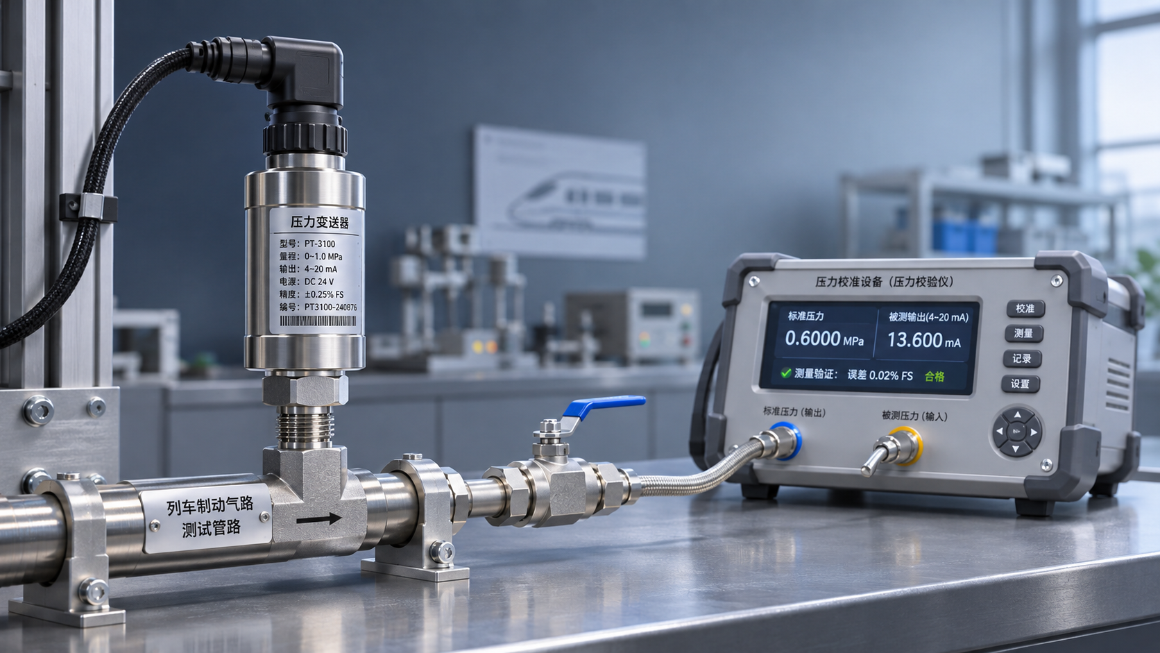
On-site verification should use a calibrated standard pressure source or reliable pressure calibration equipment. Slowly increase pressure to near the setpoint and record the alarm trigger pressure, relay status, displayed value, and PLC receiving status. Test points should preferably cover at least 25%, 50%, 75%, and 100% of the measuring range to confirm consistency between transmitter output and on-site display.
When the reading of an on-site display pressure transmitter is inaccurate, first check the supply voltage, wiring terminals, grounding and shielding, liquid accumulation or blockage in the impulse line, installation-location vibration, and range matching. A 4–20 mA signal across a 250 Ω load resistor typically corresponds to a 1–5 V voltage signal, which can assist in determining whether the loop has insufficient power supply, poor contact, or signal attenuation.
When remote pressure transmitter wiring is long, shielded cable with a suitable conductor size should be selected, and power cables should be routed separately from signal cables. For transmission distances from tens to hundreds of meters, the total loop load and power supply margin should be calculated. For wireless pressure transmitters, communication coverage, reporting cycle, battery life, and data refresh requirements need to be evaluated; wireless methods must not replace protection circuits requiring real-time interlocking.
Pressure Transmitter Selection and Threshold Configuration Should Be Carried Out Simultaneously
The setting method for an adjustable pressure transmitter range should be based on the actual maximum pressure, overload capacity, and measurement resolution. An excessively large range reduces the likelihood of overrange but lowers resolution in the low-pressure section. An excessively small range may damage the sensing element due to pressure impact. Under normal conditions, long-term operating pressure should preferably be maintained within 30%–70% of full scale.
Compared with mechanical pressure gauges, electronic pressure transmitters are better suited to systems requiring remote transmission, upper and lower limit alarms, automatic control, and data acquisition. Mechanical instruments are suitable for quick on-site observation and simple inspection. The two may be used together, but automation control thresholds should be based on calibrated electronic signals and must not rely solely on manual gauge observation.
Relying on its brand operation, sales, and technical service system, Xi'an Shenghongchuang Instrument Co., Ltd., together with the standardized manufacturing capabilities of Shaanxi Qinkong Sensor Technology Co., Ltd., can provide industrial pressure transmitter selection recommendations based on the medium, pressure range, installation interface, signal type, protection rating, and control requirements. Before determining the trigger threshold for an alarm pressure transmitter, it is recommended to compile the allowable equipment pressure, historical fluctuation data, alarm response procedures, and wiring requirements, and have professional technical personnel complete parameter confirmation and on-site commissioning.
- Pressure Transmitter
- 工业压力变送器
- Differential Pressure Transmitter
- Wireless Pressure Transmitter
- Remote Pressure Transmitter
- On-Site Display Pressure Transmitter
- Pressure Transmitter with Relay Output
- Alarm Pressure Transmitter
- Adjustable Pressure Transmitter
- Electronic Pressure Transmitter
- How to Set the Range of an Adjustable Pressure Transmitter
- How to Set the Alarm Trigger Threshold for a Pressure Transmitter
Related Recommendations
 What validation items should be considered when using railway pressure transmitters in train braking systems?
 Measuring Point and Installation Plan for Hydropower Pressure Transmitters in Turbine Governor Systems
 What Can Hydraulic Pressure Transmitters Measure? Applications from Reservoir Water Levels to Pipeline Pressure
 Connecting an RS232 Pressure Transmitter to a Host Computer: Serial Port Parameters and Communication Troubleshooting