News Center
—— NEWS CENTER ——
Xi'an Shenghongchuang Instrument Co., Ltd.
Contact: Mr. Zhang
Mobile: 15529283736
Email: shc-sensor@qq.com
Address: Fortune Building, Sanqiao Street, Xixian New Area, Xi'an, Shaanxi Province
How to Compare Electronic Pressure Transmitters and Mechanical Instruments When Purchasing
In equipment retrofitting, pipeline integration, or new automated production lines, pressure measurement solutions often require a choice between electronic pressure transmitters and mechanical pressure gauges. Both can indicate medium pressure, but they differ in measurement principles, data usage, maintenance cycles, and system compatibility. Judging solely by the purchase price of a single unit can easily overlook subsequent costs such as wiring, inspection rounds, interlocking, and downtime maintenance.
Mechanical pressure gauges typically use a Bourdon tube structure and display pressure directly through a pointer. They are suitable for applications where personnel can conduct close-range inspections, the environment is relatively stable, and data upload is not required. Electronic pressure transmitters convert pressure signals into 4-20mA, 0-10V, RS485, or switching signals, which can be connected to PLCs, DCSs, variable frequency drives, or intelligent digital display control instruments.
For industries such as machinery manufacturing, chemical energy, water and gas supply, and intelligent equipment, selection should not focus only on “whether pressure can be measured.” Attention should also be paid to the pressure fluctuation range, control accuracy, installation location, medium characteristics, environmental rating, and whether remote monitoring and alarm interlocking will be needed in the future.
Relying on the production and testing capabilities of Shaanxi Qinkong Sensor Technology Co., Ltd., Xi'an Shenghongchuang Instrumentation Co., Ltd. can provide pressure transmitters, supporting intelligent digital display control instruments, and customized measurement and control solutions to help users complete an overall configuration from field measurement to control execution according to actual operating conditions.
I. Core Differences: Display Tools vs. Control Signal Sources
Mechanical Pressure Gauges Are Suitable for Direct Inspection
The advantages of mechanical pressure gauges are their intuitive structure, no need for external power supply, and the ability to directly read the pointer position after installation. In air compressors, ordinary water pumps, storage tanks with low-frequency use, and temporary inspection stations, operators can quickly determine from the dial whether the pressure is within a roughly normal range.
However, pointer readings are subject to parallax, and personnel need to arrive at the site to confirm the data. For pipelines distributed over long distances, measurement points inside enclosed equipment, or unattended areas, relying solely on mechanical gauges increases the frequency of manual inspections and makes it difficult to create continuous records of pressure changes.
Vibration, pulsating pressure, and corrosive media also require particular consideration for mechanical gauges. Pump outlets, hydraulic stations, and compressor outlets are often accompanied by pressure shocks. Without buffer tubes, dampers, or anti-vibration structures, pointer vibration can affect observation, and internal movements may also wear more quickly.
Therefore, mechanical gauges are more suitable as local observation instruments or as auxiliary verification devices alongside electronic measurement systems, rather than as the sole pressure data source under all operating conditions.
Electronic Pressure Transmitters Are Suitable for Automated Closed-Loop Control
Electronic pressure transmitters collect pressure through sensing elements and output standard signals after amplification, compensation, and conversion. 4-20mA is commonly used in industrial fields, where 4mA typically corresponds to the lower range limit and 20mA corresponds to the upper range limit, meeting both long-distance transmission and wire-break detection requirements.
When the signal enters a PLC or digital display controller, the system can control pump start/stop, variable frequency drive frequency, solenoid valve operation, or alarm status based on real-time pressure. For example, if the operating pressure is set at 0.60MPa, pressure replenishment can start at 0.50MPa and equipment can stop at 0.65MPa, reducing energy consumption and mechanical shock caused by frequent starts and stops.
For applications requiring trend analysis, electronic transmitters can also upload data to a host computer or platform. Maintenance personnel can check whether pressure drops abnormally within a short period or whether periodic peaks occur, helping identify issues such as leakage, filter element blockage, and reduced pump efficiency.
If both on-site readings and control are required, a pressure transmitter with local display can be selected, or a standard transmitter can be used together with an intelligent digital display control instrument, allowing on-site observation and remote management to be completed simultaneously.
II. Accuracy, Range, and Response: Do Not Look Only at Dial Graduations
Accuracy Class Must Match the Control Objective
Common accuracy classes for mechanical pressure gauges include Class 1.6 and Class 1.0, which are suitable for general observation requirements. Electronic pressure transmitters are commonly specified by full-scale accuracy, such as 0.5%FS and 0.25%FS. Taking a 0-1.0MPa range as an example, the theoretical allowable error of 0.5%FS is approximately plus or minus 0.005MPa.
For ordinary water supply and pneumatic auxiliary pipelines, Class 1.0 or 0.5%FS products can generally meet requirements. For operating conditions such as test equipment, precision hydraulic control, and batching control, a higher accuracy class should be selected based on allowable process deviation, while considering temperature effects and long-term stability.
It should be noted that accuracy does not equal actual system accuracy. Sensor error, installation location, medium pulsation, electrical interference, and instrument input error all affect the final result. If the control target is plus or minus 0.01MPa, a single component with a nominal accuracy close to that value cannot simply be selected.
When purchasing, the three concepts of “measurement accuracy,” “repeatability,” and “long-term stability” should be clarified, and the supplier should be required to confirm its test conditions. For critical measurement points, it is recommended to allow approximately 20% accuracy margin to avoid approaching process boundaries after long-term operation.
Range Selection Should Be Focused on the Commonly Used Pressure Section
When the range is too large, normal pressure changes are concentrated within a very small section of the range, reducing both reading resolution and control sensitivity. If the range is too small, overload may occur during pressure shocks, causing damage to sensing elements or abnormal output.
Generally, for stable pressure, the maximum operating pressure may be selected within a range of approximately 60% to 80% of full scale. If frequent pulsation, startup shock, or short-term overpressure exists, the range should be increased based on peak pressure, and buffering or pressure-limiting measures should be added at the process end.
For example, if a system normally operates at 0.8MPa and the short-term peak can reach 1.1MPa, selecting a 0-1.0MPa range may present an overpressure risk. Selecting a 0-1.6MPa or 0-2.0MPa range is generally more reliable, but it is still necessary to verify whether the control resolution meets requirements.
Intelligent products with adjustable ranges are suitable for equipment with multiple specifications or retrofit projects, but parameter settings must be documented to prevent misjudgment during subsequent maintenance due to inconsistencies between the range and PLC engineering values.
III. Environmental Adaptability: Complex Operating Conditions Require Attention to Structural Details
Protection Rating and Installation Location Must Be Considered Together
In environments such as workshop washdown areas, outdoor station buildings, and damp tunnels, the enclosure protection capability of instruments directly affects service life. IP65 can generally handle ordinary dust and spray environments, while IP67 is more suitable for equipment areas with a higher risk of temporary immersion. However, actual selection should still verify connectors, cable outlets, and installation methods.
The junction boxes, aviation connectors, and cable sealing components of electronic pressure transmitters must be fully matched. Even if the transmitter body has a high protection rating, exposed field cables, unlocked connectors, or upward-facing cable entries that collect water may still cause signal drift, short circuits, or communication interruptions.
Mechanical gauges may likewise experience fogging of the gauge glass, blurred graduations, or internal corrosion in humid environments. For long-term outdoor use, models with stainless steel enclosures and better sealing structures should be selected, along with sun protection, rain protection, and vibration-reduction installation measures.
If the medium temperature exceeds the allowable range of the transmitter, the sensor should not be installed directly at the high-temperature medium outlet. Heat transfer can be reduced through impulse piping for heat dissipation, condensate bends, isolators, or remote seal structures to prevent zero drift and seal aging.
Interference Resistance and Vibration Resistance Determine Long-Term Stability
Where strong electromagnetic interference exists near motors, variable frequency drives, and welding equipment, electronic transmitters should use shielded cables, and signal lines should avoid being laid parallel to power lines whenever possible. Compared with ordinary voltage signals, 4-20mA current signals are generally better suited to long-distance transmission in industrial fields.
For high-vibration equipment such as hydraulic presses, compressors, and construction machinery, pressure tapping ports should avoid intense vibration sources as much as possible. Oil-filled anti-vibration models can be selected for mechanical gauges, while electronic pressure transmitters require confirmation of vibration resistance rating, installation thread strength, and connector locking method.
When pressure changes very quickly, an excessively short sampling cycle may directly transmit pulses into the control system, causing frequent relay operation. System stability can be improved by setting software filtering, delay control, upper and lower limit hysteresis, or adding mechanical damping.
Based on medium temperature, viscosity, corrosiveness, vibration level, and signal interface, Shenghongchuang can match different solutions including diffused silicon, ceramic capacitance, flush diaphragm, and diaphragm structures, reducing problems caused by mismatches between product parameters and site conditions.
IV. Total Cost Assessment: A Low Purchase Price Does Not Mean a Low Cost of Use
Include Manual Inspection and Downtime Risks in the Calculation
The initial purchase and installation costs of mechanical pressure gauges are generally lower, but when the number of measurement points increases to 20, 50, or even more, manual inspection, recording, verification, and abnormality tracing consume considerable time. For production lines requiring 24-hour operation, pressure abnormalities that are not identified in time may also increase downtime losses.
Electronic pressure transmitters require power supply, wiring, and control system interfaces, resulting in relatively higher initial investment. However, they can automatically collect data, trigger alarms, and participate in closed-loop control. Their overall management efficiency is generally higher, especially in multi-pump coordinated control, centralized gas supply, environmental protection equipment, and automated production lines.
From a maintenance perspective, both types of products should be included in a verification system. For critical measurement points, periodic verification or calibration is recommended according to equipment operating intensity. When abnormal zero points, unstable output, damaged dials, or seal leakage are found, they should be addressed promptly rather than replaced only after a process accident occurs.
A more reasonable approach is often not to choose one over the other, but to use electronic pressure transmitters at critical control points and retain mechanical gauges at auxiliary locations convenient for observation. This meets automatic control requirements while allowing field personnel to quickly verify the actual status.
V. Practical Selection Steps for Pressure Measurement Solutions
Confirm the Process First, Then Determine Product Parameters
The first step is to collect the maximum operating pressure, normal pressure, medium temperature, medium composition, installation interface, and on-site power supply conditions. For steam, viscous liquids, particle-containing media, or corrosive liquids, it is also necessary to confirm in advance whether diaphragms, heat dissipation, or special diaphragm materials are required.
The second step is to define the purpose of the data. If only manual inspection is required, mechanical instruments can be considered first. If remote display, historical records, or variable frequency control are required, standard-signal electronic pressure transmitters should be selected. If local over-limit alarms are required, pressure control products with relay outputs can be selected or used with intelligent digital display control instruments.
The third step is to verify electrical and mechanical interfaces. Common process connections include G1/4, G1/2, and M20×1.5, while signal interfaces may include two-wire 4-20mA, three-wire voltage output, or RS485 communication. Inconsistent interfaces increase the need for adapters and potential faults, so they should be confirmed before placing an order.
Finally, actual operating-condition trial runs should be used to verify the range, alarm thresholds, and control hysteresis. For batch projects, it is recommended to first complete prototype testing at 1 to 2 representative measurement points before large-scale configuration, ensuring that measurement accuracy, operational stability, and maintenance convenience all meet on-site requirements.
If you are comparing electronic pressure transmitters and mechanical pressure gauges, you may compile your existing pressure range, medium, installation thread, output signal, and operating environment, then contact Xi'an Shenghongchuang Instrumentation Co., Ltd. for targeted selection recommendations, product parameter confirmation, and supporting industrial measurement and control solutions.
Related Recommendations
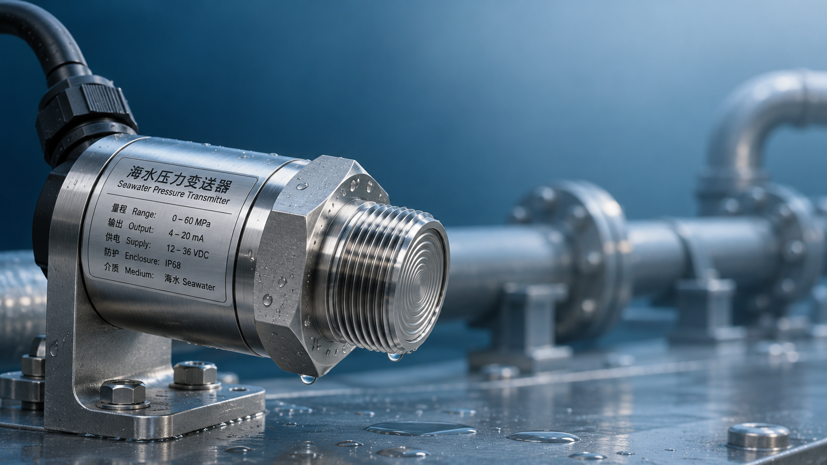
 How to Choose Wetted Materials for Seawater Pressure Transmitters: Titanium Alloy vs. Stainless Steel Corrosion Resistance
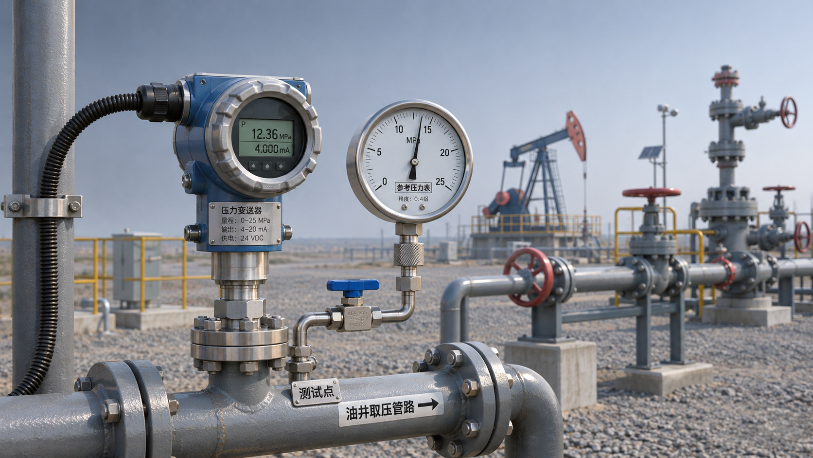
 Common Causes of Reading Drift in Oil Well Pressure Transmitters and On-Site Troubleshooting Methods
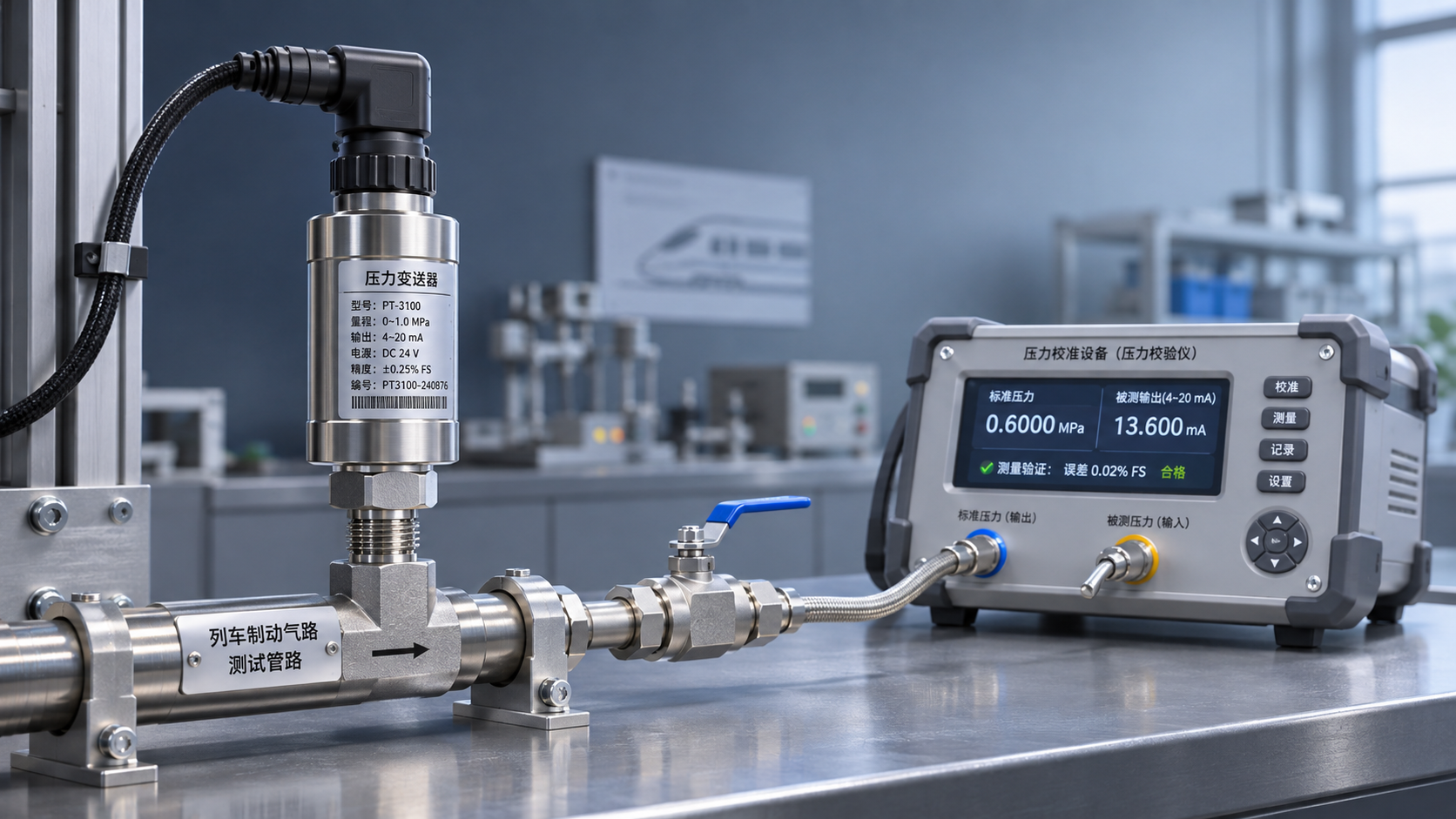
 What validation items should be considered when using railway pressure transmitters in train braking systems?
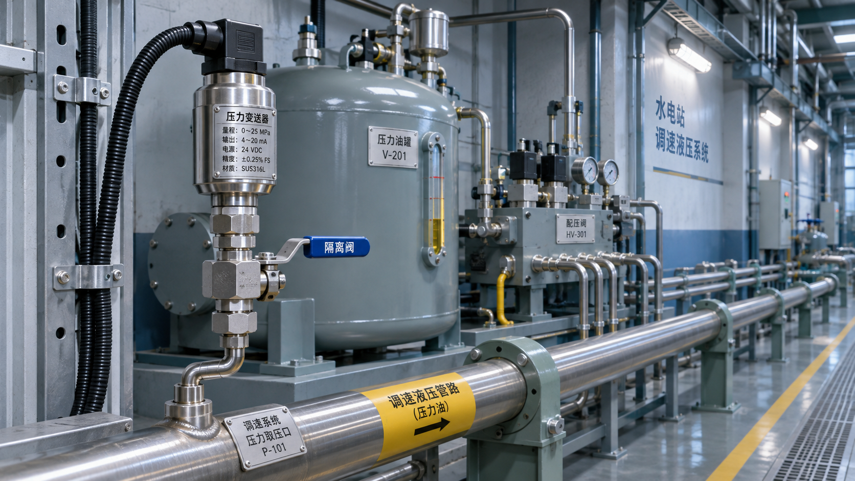
 Measuring Point and Installation Plan for Hydropower Pressure Transmitters in Turbine Governor Systems