News Center
—— NEWS CENTER ——
Xi'an Shenghongchuang Instrument Co., Ltd.
Contact: Mr. Zhang
Mobile: 15529283736
Email: shc-sensor@qq.com
Address: Fortune Building, Sanqiao Street, Xixian New Area, Xi'an, Shaanxi Province
Where Do Errors in High-Accuracy Level Sensors Come From?
A high-accuracy level sensor does not necessarily maintain the same measurement results under all field conditions. The accuracy stated on the product nameplate is typically a laboratory specification obtained under specified temperature, standard medium, stable installation, and rated range conditions. Once used in storage tanks, reactors, sewage pools, or chemical containers, actual errors can also be affected by medium density, temperature fluctuations, foam, pressure changes, and mechanical vibration.
Taking a common pressure-type level transmitter as an example, if the range is 0–5 m and the accuracy is 0.25%FS, the theoretical basic error is approximately ±12.5 mm. If the on-site liquid density deviates from the calibrated value by 5%, the converted level result may also show a deviation close to 5%. Therefore, the accuracy grade of the sensor itself should not be considered in isolation.
For level monitoring projects requiring low error, “sensor accuracy, operating-condition-induced error, installation error, and display and control error” should be evaluated separately. In actual engineering applications, the overall system error is often higher than the factory accuracy of a single level sensor. Proper selection and standardized commissioning are more important than simply pursuing higher specifications.
Accuracy Grade and Overall Measurement Error Should Not Be Confused
Specifications such as 0.1%FS, 0.25%FS, and 0.5%FS accuracy usually refer to full-scale referenced error. For example, for a product with a 10 m range, 0.5%FS corresponds to an allowable basic error of approximately ±50 mm; when the same accuracy grade is used for a 2 m range, the allowable error is approximately ±10 mm. As the range increases, the absolute error increases accordingly.
If the liquid level changes only within a small range, blindly selecting an excessively large range will reduce effective resolution. For example, if the actual liquid-level variation is 0.5–2.5 m, a 0–10 m range can be used, but it is less advantageous for detecting small level changes than a 0–3 m or 0–4 m range.
Repeatability, stability, and long-term drift should also be distinguished during selection. Repeatability reflects the dispersion of repeated measurements at the same liquid level, while long-term drift relates to the reliability of readings after months or years of operation. For continuous production equipment, calibration results after 12 months of stable operation are often more important than the initial displayed values.
Practical Methods for Determining Whether Error Is “Excessive”
First, verify the sensor range, accuracy grade, output signal, and calibration medium, and confirm whether on-site readings are converted using the correct density. For products with 4–20mA output, 4mA usually corresponds to zero level and 20mA to full scale. Voltage drop at wiring terminals, insufficient power supply, or poor loop contact can also cause abnormal display values.
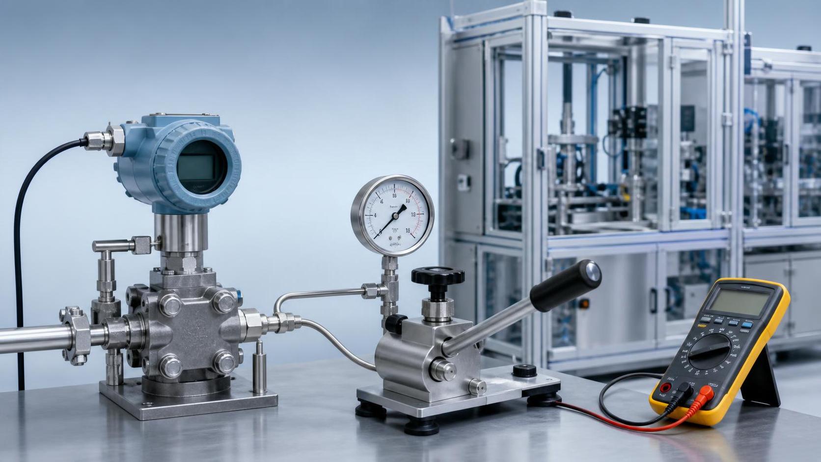
Second, use reliable references for comparison, such as manual tape measurement, calculated hydrostatic pressure values, verified liquid levels, or volume conversion results. Verification is recommended at 25%, 50%, and 75% level points rather than comparing only once at full scale, in order to identify zero drift, linear deviation, or installation height error.
Finally, observe whether the error follows a pattern. Readings that are consistently high or low are usually related to the zero point, installation reference, or density setting; randomly fluctuating readings require focused inspection of agitation, liquid-surface fluctuations, electromagnetic interference, probe water ingress, and signal cable shielding and grounding.
Key Operating Conditions Affecting the Actual Accuracy of Level Sensors
Medium characteristics are the primary factor in determining whether the error of a high-accuracy level sensor is significant. Measurement conditions differ considerably for clean water, oils, slurry, corrosive solutions, and liquids containing bubbles. Pressure-type products calculate liquid level based on hydrostatic pressure from the liquid column. When density varies significantly, parameters should be corrected promptly or a more suitable measurement principle should be selected.
Temperature changes also affect measurement stability. High-temperature media may subject sensing elements, sealing structures, and pressure-guiding components to additional thermal stress; low-temperature environments may cause increased medium viscosity, condensation, or crystallization. For operating conditions with temperatures exceeding 80℃ for extended periods, the temperature resistance range of the isolating diaphragm, fill fluid, and process connection components should be confirmed.
When strong agitation, pump starting and stopping, tank vibration, or liquid-surface turbulence is present, the instantaneous liquid level itself is changing. In such cases, sensor display fluctuations do not necessarily indicate inaccurate measurement. In engineering applications, a more representative average level value can be obtained through damping time, signal filtering, hydrostatic guide pipe arrangement, or installation of a stilling well.
Comparison of Accuracy and Applicability of Different Level Measurement Solutions
Recommendations for corrosion-resistant level sensors cannot be made independently of the medium, pressure, and installation structure. For strong alkalis, acidic liquids, or saline wastewater, wetted materials typically require particular attention, including configurations such as 316L stainless steel, PTFE, PVDF, and ceramic diaphragms. It is also necessary to confirm whether sealing rings and process connection components provide the corresponding corrosion resistance.
Pressure-type level transmitters have a mature structure and are suitable for continuous measurement of liquids with relatively stable density. Submersible products are easy to install and are commonly used in pools, deep wells, and storage tanks. Radar level meters are suitable for high-temperature, high-pressure, or applications where direct contact with the medium is unsuitable; however, for heavy foam or low-dielectric-constant media, performance must be confirmed in conjunction with on-site reflection conditions.
Hygienic flush-diaphragm level sensors are suitable for food, pharmaceutical, fermentation, and high-viscosity media. Flush diaphragms can reduce material buildup and cleaning dead zones. During installation, the diaphragm should be protected from impact by hard objects, no obvious step should be formed at welded connections, and product suitability for CIP or SIP conditions should be confirmed according to the cleaning temperature.
How to Select a More Reliable Vibration-Resistant Level Sensor
For sites with obvious equipment vibration, such as compressor units, construction machinery, mobile tanks, and automated production lines, priority should be given to verifying the sensor’s vibration resistance rating, enclosure protection rating, connector locking structure, and cable tensile strength. Relying solely on software filtering cannot resolve issues such as loose mechanical connections, diaphragm fatigue, or vibration affecting internal components.
The installation location should be kept as far as possible from pump bodies, valve impact zones, and areas directly exposed to high-velocity fluid flow. For submersible level sensors, guide pipes or counterweight measures can be used to reduce probe movement; for flange-mounted products, the sealing surface should be flat and bolt loading should be even to prevent leakage or zero-point changes caused by long-term vibration.
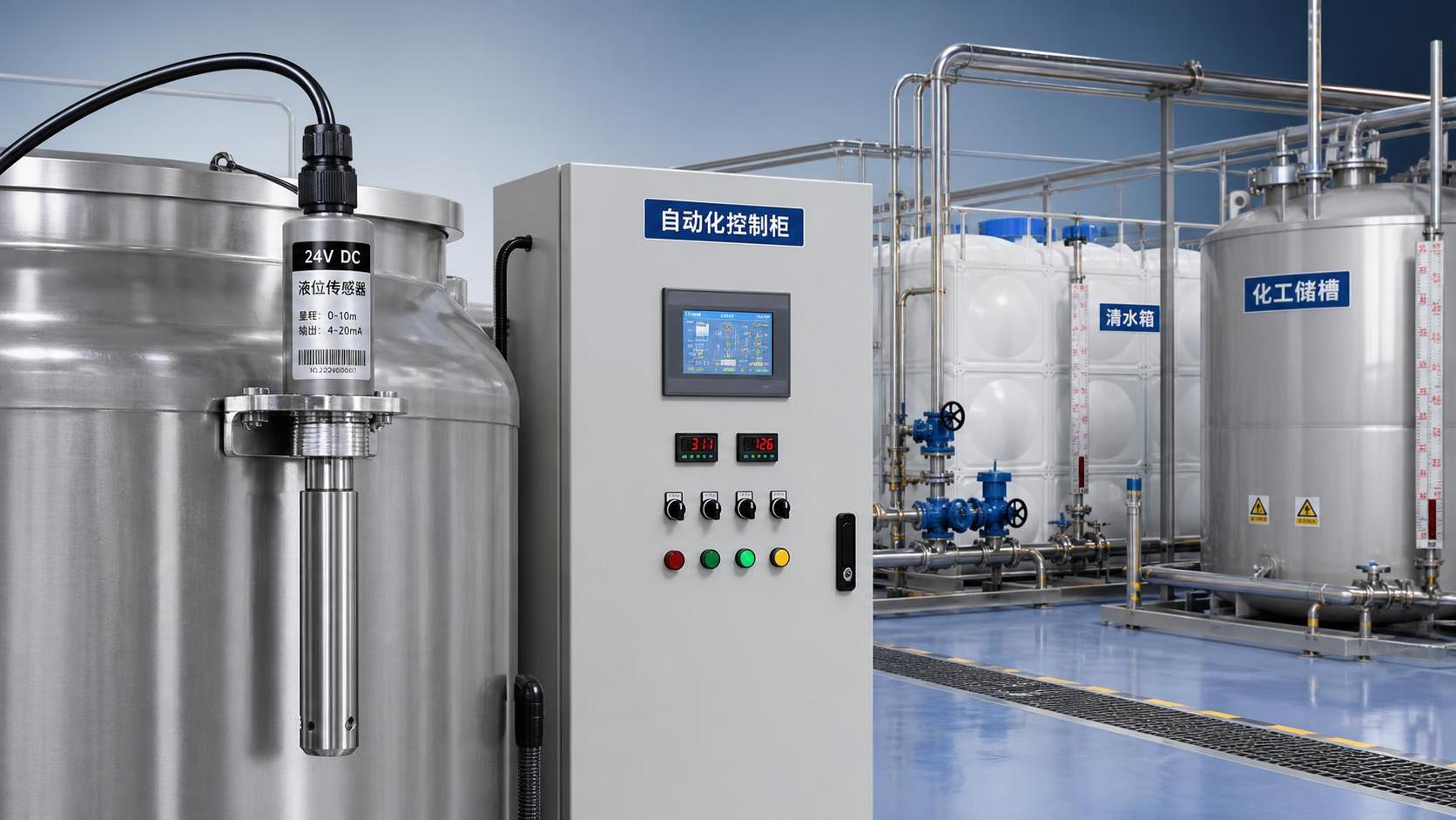
When the level signal is used for interlock control, 4–20mA output with appropriate fault-detection logic is recommended. A 24VDC power supply system should ensure that the actual voltage at the sensor meets requirements. Power cables and power lines should be routed separately, and the shielding layer is generally grounded at one end to reduce interference from variable-frequency equipment.
Key Practices for Reducing Error: From Installation and Wiring to Calibration
Before wiring a 24V-powered level sensor, first read the wiring label or product manual to identify the definitions of the positive power terminal, signal terminal, common terminal, and shield terminal. Two-wire 4–20mA products usually use the same loop for power supply and signal transmission. Incorrect parallel connection to the power supply or reverse polarity may result in no output, fixed output, or equipment damage.
The installation reference must be consistent with the control system settings. The zero point of submersible products is usually referenced to the probe measuring end, while flange-type differential pressure level transmitters must account for installation height, liquid columns in the high- and low-pressure-side impulse lines, and vessel pressure conditions. After installation, zero-point verification should be performed with an empty tank or under known liquid-level conditions.
Regular maintenance can significantly reduce long-term error. Based on medium cleanliness and process importance, inspection intervals of 3 months, 6 months, or 12 months are recommended to check for diaphragm scaling, probe corrosion, cable damage, water ingress at connectors, and abnormal displays. Calibration records and fault-handling records should be retained for critical measurement points.
Display Instrument Selection Also Affects On-Site Assessment
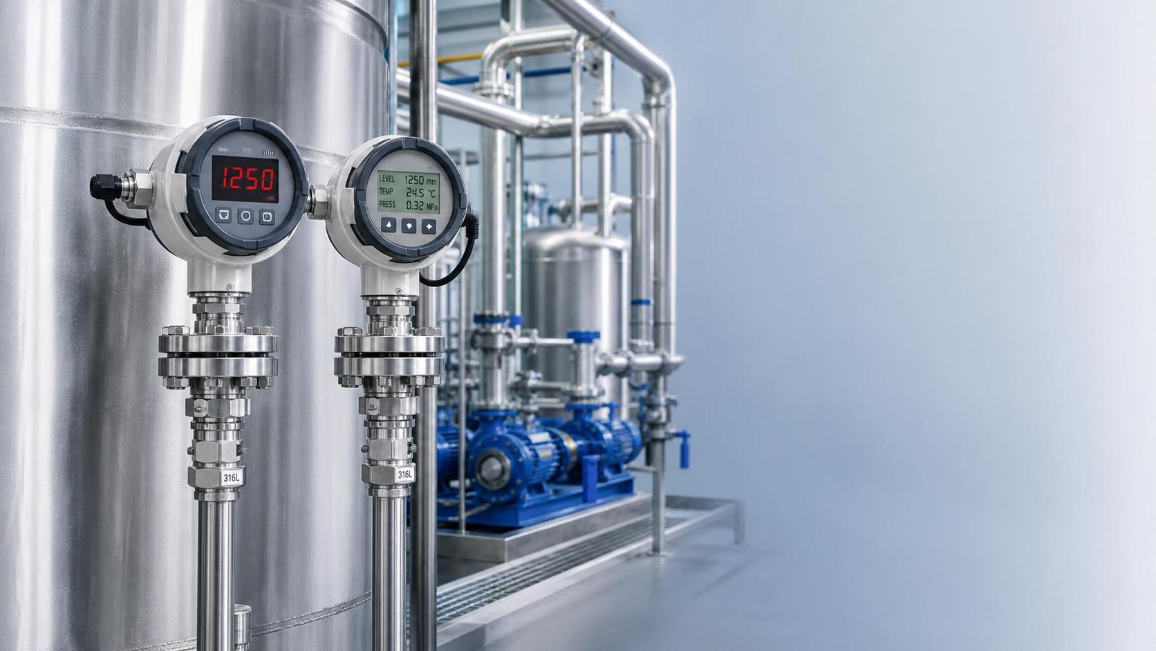
The main differences between LED level display instruments and LCD level display instruments lie in on-site visibility and information capacity. LED displays are more intuitive in dim workshops, for long-distance viewing, and where conspicuous alarms are required; LCD displays can usually show more parameters, units, and menu information, but readability should be considered in strong-light or low-temperature environments.
For applications requiring only real-time level viewing and high/low alarms, a stable digital display control instrument is sufficient. The focus should be on input signal matching, alarm relay capacity, and anti-interference design. If level, temperature, pressure, and historical trends need to be displayed, the instrument’s communication interfaces, data refresh cycle, and system compatibility should be confirmed.
Whether LED or LCD is used, the display instrument should be configured for zero point, full scale, and unit conversion. When the sensor output is 4–20mA, the instrument range should match the actual liquid-level range. For example, if 4mA corresponds to 0m and 20mA corresponds to 6m, incorrect scaling parameter settings will cause significant display deviations even if the sensor itself is accurate.
Selection Conclusions for High-Precision Level Measurement Requirements
Low-error level sensors are suitable for high-precision requirements, provided that the measurement principle matches the medium and operating conditions. For stable liquid storage tanks, high-accuracy pressure-type or differential-pressure solutions can be evaluated first; for conditions involving strong corrosion, high temperature and pressure, significant foam, or complex internal vessel structures, selection should be determined comprehensively based on corrosion-resistant materials, installation location, and measurement principle.
When purchasing, it is recommended to clearly specify the range, medium composition, density range, temperature, pressure, installation method, output signal, protection rating, and target error. For critical projects, factory inspection information, material specifications, calibration capabilities, and the boundaries of non-standard customization should also be requested, avoiding decisions based solely on price or a single accuracy parameter.
Xi'an Shenghongchuang Instrumentation Co., Ltd. can provide selection and supporting services for pressure transmitters, level transmitters, differential pressure transmitters, and intelligent digital display control instruments according to tank structure, medium corrosiveness, on-site vibration, and control requirements. By submitting information on on-site range, medium, temperature and pressure, and installation interface, you can further obtain a level measurement solution better suited to the operating conditions.