News Center
—— NEWS CENTER ——
Xi'an Shenghongchuang Instrument Co., Ltd.
Contact: Mr. Zhang
Mobile: 15529283736
Email: shc-sensor@qq.com
Address: Fortune Building, Sanqiao Street, Xixian New Area, Xi'an, Shaanxi Province
How to Select a Vibration-Resistant Level Sensor for Complex Operating Conditions
In applications near pump units, mixing tanks, mobile equipment, compressor vessels, and systems subject to frequent start-stop shocks, level measurement is not simply a matter of being able to detect the level. Continuous vibration can loosen mounting connections, fatigue pressure-guiding structures, and cause unstable contact in internal circuits, resulting in fluctuating readings, zero drift, signal interruption, or even false interlock actions. Vibration resistance should be regarded as a technical specification as important as measuring range and accuracy during selection.
Xi'an Shenghongchuang Instrumentation Co., Ltd., supported by the manufacturing base of Shaanxi Qinkong Sensor Technology Co., Ltd., provides level transmitters and supporting intelligent digital display control instruments for industrial automation measurement and control applications. For sites with high temperatures, high pressures, strong interference, or significant mechanical vibration, a comprehensive evaluation should be conducted from five dimensions: sensing principle, wetted material, mounting structure, output method, and process connection. Model selection should not be based solely on price or nameplate accuracy.
In general, vibration-resistant level sensors should first be selected by identifying the source of vibration and its transmission path on site. Continuous vibration generated by motors and pumps, transient shocks caused by valve opening and closing, and random vibration from vehicle transportation require different structural reinforcement priorities. For equipment operating continuously over long periods, the long-term repeatability of the sensor under vibration should also be considered rather than relying only on static calibration data.
A proper selection process should be based on actual operating-condition data: medium density, temperature range, corrosiveness, vessel pressure, mounting position, maximum level fluctuation, power supply conditions, and control system interface must all be determined in advance. More complete information helps prevent problems after installation, such as mismatched measuring ranges, corrosion of wetted components, or signals that cannot be connected to the PLC.
I. Identify Vibration Conditions and Measurement Risks First
Vibration Is Not a Single Parameter: Frequency, Amplitude, and Impact Mode Must Be Distinguished
Before selection, the vibration level can be confirmed through site inspections, equipment technical documentation, or vibration testing. Common engineering vibration frequencies range from 10Hz to 500Hz. Different frequency bands affect sensor housings, connectors, internal solder joints, and sensing elements differently. If the equipment is subject to intermittent strong impacts, the product's impact resistance and mounting support solution should also be carefully verified.
For level sensors installed on pump outlet pipelines, circulation tanks, or mixing vessels, liquid level fluctuations are often superimposed on mechanical vibration. Even if the sensor itself has good vibration resistance, undamped process pressure fluctuations may be converted into continuously changing output signals, causing unstable display readings on the control interface.
It is recommended to assess “mechanical vibration” and “level disturbance” separately. Mechanical vibration primarily affects equipment reliability, while level disturbance primarily affects measurement stability. The former should be addressed by reinforced mounting and vibration-resistant structures; the latter can be improved by using guide wave tubes, optimizing hydrostatic pressure tapping locations, and setting instrument damping time.
When large motors, frequency converters, or high-frequency switching equipment are present on site, electromagnetic interference should also be evaluated. A 4mA to 20mA analog output is generally suitable for long-distance transmission in industrial environments. Combined with shielded cables, reliable grounding, and proper cable routing, it can reduce the risk of electrical interference under vibration conditions being misidentified as a “sensor fault.”
II. Select Corrosion-Resistant Wetted Materials Based on Medium Characteristics
Are Level Sensors for Strong Alkalis Corrosion-Resistant?
Whether a level sensor for strong alkalis can resist corrosion over the long term depends primarily on whether the wetted diaphragm, sealing rings, process connection, and fill fluid are compatible with the specific medium. It should not be assumed that “stainless steel” is suitable for all alkaline solutions. For media such as sodium hydroxide and potassium hydroxide, concentration, temperature, chloride ion content, and the presence of crystalline deposits must also be specified.
For conventional industrial environments, wetted solutions such as 316L stainless steel, Hastelloy, tantalum, and PTFE can be selected according to medium conditions. For concentrated alkalis and high-temperature alkaline solutions, the resistance of sealing materials is often more easily overlooked than that of metal diaphragms. After sealing rings age, the medium may seep through connection points and affect the long-term stability of the sensor.
In alkaline solution vessels containing crystals, adhesion, or particulates, a flush diaphragm structure is generally easier to clean and can reduce the risk of cavity blockage. When sanitary flush diaphragm level sensors are used in food, pharmaceutical, fine chemical, and similar applications, clamp dimensions, surface roughness, cleaning procedures, and CIP or SIP process parameters should also be confirmed.
Before purchasing, provide technical personnel with the medium name, concentration percentage, normal and maximum temperatures, vessel pressure, and cleaning fluid information. For complex corrosive media, material compatibility should be confirmed. Where necessary, a diaphragm seal solution should be used to prevent ordinary pressure-guiding structures from directly contacting the medium.
Parameters That Must Not Be Overlooked in Corrosion-Resistant Selection
III. How to Assess Measuring Range, Accuracy, and Actual Error
Do High-Accuracy Level Sensors Have Large Errors?
A high-accuracy level sensor does not necessarily mean that its error will be extremely small in field use. The rated accuracy of a product is generally obtained under specified reference conditions, whereas actual error is jointly affected by installation height, changes in medium density, ambient temperature, process pressure, vibration, zero shift, cable interference, and other factors. Laboratory accuracy should be distinguished from system measurement accuracy.
For example, hydrostatic level measurement is directly related to medium density. If liquid density changes from 1.00g/cm³ to 0.90g/cm³, the pressure corresponding to the same liquid level height changes by approximately 10%. Such process deviation is far greater than the rated instrument accuracy of 0.1%FS or 0.25%FS. Therefore, when density fluctuations are significant, compensation methods should be evaluated or a more suitable measurement principle should be considered.
Are low-error level sensors suitable for high-precision requirements? The answer is yes, provided that the measuring range is selected appropriately. A common recommendation is to keep the normal liquid level within 30% to 80% of the sensor range. This preserves allowance for level fluctuations and over-limit conditions while avoiding insufficient effective resolution caused by an excessively large range.
For high-precision requirements such as metering, batching, and inventory accounting, it is recommended to perform a zero-point check and full-scale calibration after installation and establish a regular verification system. If the process is sensitive to level changes, appropriate safety margins should be reserved between control alarm values and limit levels to prevent frequent alarms caused by transient disturbances.
IV. Installation Method Determines the Lower Limit of Vibration Resistance
Installation Precautions for Sanitary Flush Diaphragm Level Sensors
When installing a sanitary flush diaphragm level sensor, ensure that the diaphragm is flush with the inner wall of the vessel or located where material accumulation is unlikely, avoiding dead zones in the mounting opening. For high-viscosity, easily crystallized, or particulate-containing media, narrow and long pressure-guiding holes in front of the diaphragm can easily cause blockage, residue, and incomplete cleaning.
In vibration-prone applications, sensors should not be installed directly on the most severely vibrating equipment supports or at the cantilevered ends of pipelines. A location with good vessel rigidity should be selected whenever possible, ensuring uniform stress at the connection point. After flange, threaded, or clamp installation is completed, tighten according to process specifications to avoid damaging sealing surfaces through overtightening.
Cables should have an appropriate amount of slack and must not be suspended under tension. The cable weight must not be continuously applied to connectors. Near vibration sources, metal flexible conduits, cable clamps, and independent supports may be used for fixing. Signal cables should be kept as far as possible from power cables and maintain a reasonable distance when routed in parallel.
After installation, three checks are recommended: whether the empty-tank zero point is stable, whether the output is linear as the level changes, and whether abnormal signal fluctuations occur during equipment operation. For 4mA to 20mA outputs, verify the currents corresponding to low and high liquid levels respectively, and confirm that the PLC range and display instrument range are consistent with the actual on-site height.
V. Matching Power Supply, Display, and Signal Output
How to Wire a 24V Power Supply Level Sensor
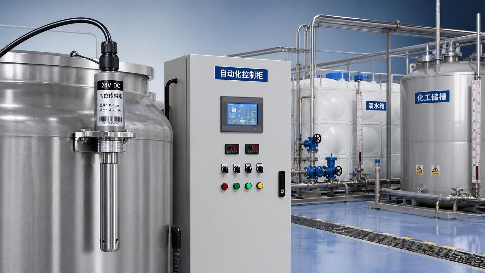
Two-wire level sensors powered by 24VDC are commonly used in 4mA to 20mA current loops. Typically, the positive terminal of the power supply is connected to the sensor power terminal, the sensor signal terminal is connected to the positive terminal of the PLC analog input, and the negative terminal of the analog input is then returned to the negative terminal of the power supply. Specific terminal definitions must follow the product wiring diagram and must not be determined solely by cable colors.
Before wiring, confirm that the actual supply voltage is within the permitted range of the device and verify that the total loop load meets requirements. When safety barriers, isolators, display instruments, or long-distance cables are connected in series in the loop, voltage drop will increase. If the voltage at the terminal is insufficient, the sensor may not be able to output 20mA normally at full scale.
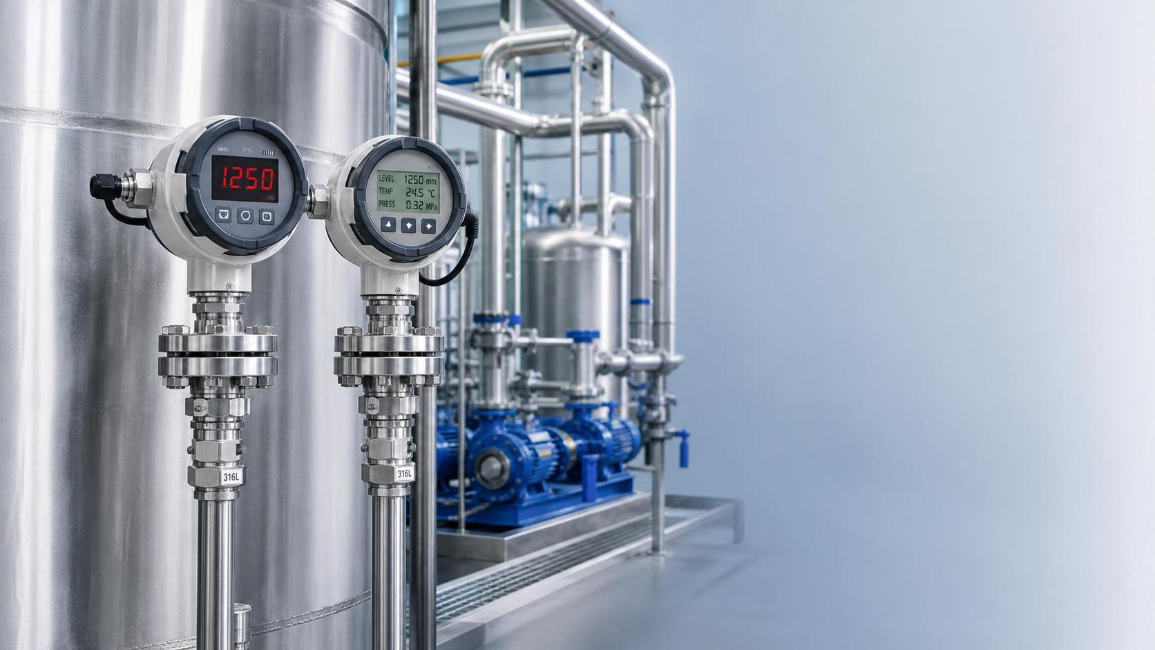
Whether an LED level sensor or an LCD level sensor is better depends on viewing distance, ambient brightness, and information requirements. LEDs generally offer higher brightness and are suitable for darker environments or equipment panels requiring long-distance viewing. LCDs consume less power and can display more character information, but their visibility under strong light and low-temperature response should be confirmed based on the specific model.
Names such as 3051, 3351, and 1151 are commonly used to describe pressure and differential pressure measurement products with different structures or series. When comparing models for level measurement applications, priority should be given to verifying turndown ratio, overload capacity, diaphragm material, process connection, communication protocol, display configuration, and protection rating, rather than making a decision based solely on series number or market price range.
VI. Establish an Actionable Selection Checklist for Vibration-Resistant Level Sensors
Recommended Items to Confirm Before Submitting Technical Parameters
First, clarify the medium and process conditions: liquid name, density, concentration, viscosity, maximum temperature, vessel pressure, corrosiveness, and whether deposits or crystallization are present. Second, clarify the measurement range: actual liquid level height, minimum and maximum levels, vessel shape, whether elevation adjustment is required, and the locations of alarm and interlock points.
Third, clarify installation and environmental conditions: interface type, mounting orientation, vibration source, ambient temperature, protection rating, explosion-proof requirements, cable length, and whether sufficient maintenance space is available on site. For outdoor equipment, actual operating conditions such as rain protection, condensation prevention, and lightning protection grounding should also be considered.
Fourth, clarify control system requirements: whether the power supply is 24VDC or another specification, whether the output uses 4mA to 20mA, RS485, or other signals, and whether local display, upper and lower limit alarms, remote communication, or supporting use with intelligent digital display control instruments is required. Complete interface information can reduce subsequent commissioning time.
For complex level measurement projects involving vibration, corrosion, high temperature and pressure, or high accuracy, the above operating-condition parameters can be compiled and submitted to the technical team of Xi'an Shenghongchuang Instrumentation Co., Ltd. Professional personnel can match suitable models based on the production process, wetted materials, mounting structure, and signal solution, and provide level measurement and control configuration recommendations better suited to the site.