News Center
—— NEWS CENTER ——
Xi'an Shenghongchuang Instrument Co., Ltd.
Contact: Mr. Zhang
Mobile: 15529283736
Email: shc-sensor@qq.com
Address: Fortune Building, Sanqiao Street, Xixian New Area, Xi'an, Shaanxi Province
Are low-error level sensors suitable for high-precision requirements? First, clarify what “error” specifically means
Level sensors with low error are generally more suitable for high-precision level measurement requirements, but whether they meet on-site requirements cannot be determined solely from specifications such as “accuracy 0.2%FS” or “error ±0.5%FS” in a product catalog. For applications such as storage tank metering, chemical batching, pharmaceutical liquid control, and process interlocking, the final measurement performance is also affected by measurement range, medium density, temperature, pressure fluctuations, installation position, and signal processing method.
Taking a level sensor with a range of 1000 mm as an example, if its overall accuracy is ±0.2%FS, the theoretical maximum error is approximately ±2 mm. If the range is expanded to 5000 mm, the same 0.2%FS corresponds to an error of approximately ±10 mm. Therefore, products with the same stated accuracy may have different actual level deviations at different ranges. For high-precision requirements, the range and accuracy grade should first be determined based on the allowable absolute error.
It is also necessary to distinguish among indicators such as basic accuracy, nonlinearity, repeatability, hysteresis, and temperature drift. Some level transmitters may have low error when calibrated at room temperature, but when the medium temperature changes from 20℃ to 80℃, zero drift, changes in diaphragm pressure conditions, or temperature drift of electronic components can all affect output stability. Therefore, a high-accuracy level sensor does not mean that the error will be low under all operating conditions.
Xi'an Shenghongchuang Instrumentation Co., Ltd. and its subsidiary, Shaanxi Qinkong Sensor Technology Co., Ltd., generally first verify the actual measurement height, medium corrosiveness, vessel pressure, temperature range, and control objectives when configuring level measurement and control solutions. They then match structures such as submersible, hydrostatic, differential-pressure, or flush-diaphragm types to avoid situations where “the parameters appear high, but the on-site deviation is large.”
Which parameters should be prioritized for high-precision level measurement?
The first item is range matching. It is generally recommended that the normal liquid level be within 30% to 80% of the sensor range. This both leaves margin for level fluctuations and reduces the amplification of absolute error caused by an excessively large range. For example, when the actual level variation range is 0 to 2 m, a 2.5 m, 3 m, or operating-condition-customized range should be considered first, rather than directly selecting a 10 m range product.
The second item is output signal and acquisition accuracy. A 4-20mA output provides strong interference resistance and is suitable for long-distance transmission in industrial environments. Only when the control system has a high-resolution analog input module can sensor accuracy be more fully converted into control accuracy. If the PLC analog module itself has an error of ±0.5%, the overall system accuracy will still be limited even if the sensor accuracy reaches ±0.1%FS.
The third item is long-term stability. High-precision requirements should not focus only on the initial calibration result; zero stability, annual drift, and repeated measurement performance should also be considered. For continuous production equipment, the annual overall drift can be controlled within ±0.2%FS to ±0.5%FS, and a 6-month or 12-month calibration plan can be established based on operating frequency and medium characteristics.
The fourth item is installation conditions. The probe position of a hydrostatic level sensor, the sealing condition of the vented cable, liquid surface disturbance in the vessel, and pump vibration may all cause output fluctuations. For projects requiring level control error not to exceed ±5 mm, the importance of the installation scheme and signal filtering settings is generally no less than that of the sensor's own accuracy.
Practical significance of common accuracy indicators for high-precision applications
From a practical project perspective, level control accuracy should be evaluated based on the total error of “sensor + installation + wiring + acquisition module + control logic,” rather than only the highest stated accuracy of a single component. For high-precision storage tank metering, it is recommended to conduct joint verification at no fewer than three measurement points—zero, full scale, and an intermediate point—before commissioning the equipment.
If on-site level fluctuations are rapid, a reasonable filtering time of 1 to 5 seconds can be set in the control system to reduce transient fluctuations caused by liquid surface sloshing. However, excessive filtering time will reduce control response speed. High precision and fast response are not entirely contradictory and should be balanced according to the process cycle.
For liquids with significant density changes, hydrostatic level measurement requires particular caution. Level height is directly related to pressure and medium density. When density changes from 1.00g/cm³ to 1.10g/cm³, if the system still converts based on a fixed density, the level result may produce a conversion deviation close to 10%. In this case, density compensation should be used or a more suitable measurement solution should be selected.
If a level sensor has low error, why can on-site measurement still be unstable?
A high-accuracy level sensor may perform well under laboratory or factory calibration conditions, but this does not mean there will necessarily be no fluctuations after installation in a complex field environment. Industrial sites involve factors such as electromagnetic interference, liquid surface turbulence, temperature cycling, tank pressure changes, crystallization buildup, and mechanical vibration, any of which may cause the output signal to deviate from its ideal state.
For submersible level sensors, moisture or blockage in the vent tube is a relatively common issue. The venting system is used to balance atmospheric pressure. If moisture enters the interior of the cable and forms condensate, the zero point may drift with changes in air pressure and temperature. For outdoor installations, the sealing of the junction box, waterproof breathable structure, and cable routing should be carefully checked.
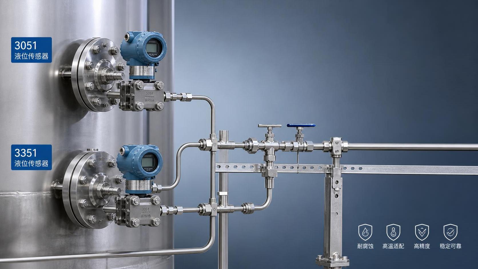
For closed vessels, if the tank pressure is between 0.1MPa and 1.6MPa, an ordinary gauge-pressure level sensor cannot be directly regarded as representing level height. Such operating conditions generally require differential-pressure level measurement, which simultaneously measures the high-pressure and low-pressure sides and uses differential pressure to eliminate the effect of gas-phase pressure at the top of the vessel.
For agitated tanks, pump stations, vehicle-mounted tanks, or vibrating equipment, the sensor probe may continuously withstand impacts and high-frequency vibration. Even if the product itself has strong vibration resistance, output stability should be improved by avoiding impact zones, installing a stilling tube, optimizing the probe fixing method, and applying software damping.
How should a vibration-resistant level sensor be selected?
Selection of a vibration-resistant level sensor should begin by confirming the vibration source and vibration mode. Pumps, compressors, and mechanical transmission equipment generally generate continuous vibration, while logistics equipment, construction machinery, and mobile storage tanks may experience intermittent impacts. Different vibration conditions impose different requirements on sensor structural strength, internal potting process, connection method, and cable tensile strength.
In locations with obvious vibration, priority should be given to products with an integrated stainless steel structure, impact-resistant sensing element, reliable potting process, and reinforced cable. For applications in which the probe is immersed in liquid for extended periods, 316L stainless steel, PTFE, or other wetted materials compatible with the medium are recommended to prevent vibration and corrosion from jointly causing sealing failure.
The installation location should avoid areas subject to direct liquid impact whenever possible, such as pump outlets, below liquid inlets, near agitator blades, and high-drop return points. If installation near a disturbance area is unavoidable, a stilling pipe, guide cylinder, or protective sleeve can be installed so that the sensor measures a relatively stable hydrostatic liquid column rather than continuously changing impact pressure.
On the signal side, a 4-20mA two-wire output can be used with shielded cable grounded reliably at one end. The power supply should be routed separately from variable-frequency drives and motor power cables, and crossings should be kept at a 90-degree angle whenever possible. For 24V-powered level sensors, the power supply ripple and load capacity should meet equipment requirements to prevent unstable power supply from being misidentified as a sensor fault.
Reference for selecting level sensors under different operating conditions
For high-precision requirements, measurement accuracy should not be judged simply by “small fluctuations.” In some sites, excessively long filtering times reduce display fluctuations, but actual level changes are reflected with delay. The raw signal, real-time level, filtered displayed value, and response of the control valve or pump should all be checked.
Under high-temperature, high-pressure, and high-interference conditions, appropriate selection generally includes confirmation of medium temperature, pressure rating, protection rating, and explosion-proof requirements. If the on-site temperature is close to the sensor limit, a certain margin should be reserved. For example, if the equipment operates at 80℃ for long periods, a specification with an upper limit of only 80℃ should not be selected.
A mature level measurement and control solution should incorporate fault prevention into the design stage, including sensor maintenance space, spare interfaces, isolation valves, drain ports, wiring protection, and conditions for periodic calibration. This not only improves measurement reliability but also reduces downtime for subsequent maintenance.
Are strong-alkali level sensors corrosion-resistant? Material compatibility is more important than accuracy
Whether a strong-alkali level sensor is corrosion-resistant cannot be determined solely by whether “anticorrosive” or “corrosion-resistant” is indicated in the product name. It must be evaluated based on the type, concentration, temperature, pressure, and contact time of the alkaline solution. Media such as sodium hydroxide, potassium hydroxide, and ammonia water have different corrosion mechanisms for different metallic and non-metallic materials. A material suitable at low concentration and room temperature may not necessarily be suitable under high-temperature, high-concentration conditions.
Common 316L stainless steel offers good general corrosion resistance, but it is not suitable for long-term use under all strong-alkali conditions. For alkaline solutions with higher concentration, higher temperature, or chloride ions, Hastelloy, titanium, PTFE, PVDF, ceramic diaphragms, or diaphragm seal solutions should be further evaluated to avoid leakage caused by pitting corrosion, stress corrosion, or aging of sealing materials.
Strong-alkali level measurement must also account for crystallization, adhesion, and deposition. After alkaline solution evaporates, crystals may form on the probe, flange, or pressure-guiding section, resulting in inaccurate pressure transmission. For such applications, flush-diaphragm structures, flushing connections, isolation diaphragms, or installation structures that facilitate disassembly and cleaning can be considered to reduce medium residue.
For corrosive media involving personnel safety and environmental risks, the sensor protection rating, sealing method, process connection standard, and handling method after a failure should also be verified. Level measurement should not pursue low price alone; corrosion resistance, sealing reliability, and maintenance operability during long-term operation must also be ensured.
What on-site information should be provided when recommending corrosion-resistant level sensors?
Before requesting a quotation, technical evaluators or purchasing personnel should at least clarify the medium name, concentration range, normal temperature, maximum temperature, vessel pressure, and measurement range. For example, “30% sodium hydroxide, 45℃, atmospheric pressure, measurement height 0 to 3 m” is more conducive to obtaining an accurate configuration than simply stating “measuring alkaline liquid level.”
The installation method should also be provided, including top submersion, side flange, bottom installation, sanitary clamp connection, or threaded connection. If the storage tank is closed, it is necessary to state whether the top gas-phase pressure is stable. If it is an open tank, it should be stated whether there is agitation, foam, spraying, or high-flow liquid inlet.
For applications with high hygiene requirements, such as food, pharmaceuticals, and fine chemicals, sanitary flush-diaphragm level sensors can reduce dead zones for medium residue. However, during installation, the diaphragm must be flush with the inner tank wall or extend into the tank according to process requirements. The edge of the mounting hole must not create a liquid accumulation area or cleaning blind spot.
Shaanxi Qinkong Sensor Technology Co., Ltd. can provide customized configurations for conventional and complex industrial operating conditions, including range, output mode, wetted material, process connection, and display and control accessories. For non-standard projects, medium compatibility and critical dimensions should be confirmed before production to reduce on-site rework and repeated selection costs.
Material selection checklist for strong alkalis and complex media
The reliability of corrosion-resistant level sensors comes from systematic matching rather than a single material name. Even when corrosion-resistant materials such as PTFE are used, their mechanical strength, temperature limits, and whether the specific structure is suitable for on-site pressure conditions must be confirmed.
For strong-alkali storage tanks requiring alarm interlocking, it is recommended to establish multi-level protection for high level, low level, and extreme high level. A continuous level transmitter can be used for real-time monitoring, while an independent level switch can serve as a safety redundancy to reduce overflow risks caused by single-point failures.
After equipment is put into operation, an initial inspection record should be established to retain data such as zero point, full scale, medium temperature, output current, and installation condition. If a level offset corresponding to 4mA, insufficient 20mA output, or display jumping subsequently occurs, it can be determined more quickly whether the issue is with the sensor, wiring, or changing operating conditions.
How should a 24V-powered level sensor be wired to ensure accurate measurement?
A 24V-powered level sensor commonly uses a two-wire 4-20mA output. The wiring principle is that the positive power terminal connects to the sensor positive supply terminal, while the sensor signal loop passes through the PLC, display instrument, or safety barrier and then returns to the negative power terminal. Wire color definitions may vary among different models. Actual wiring must be based on the product label, wiring diagram, and instruction manual, not solely on cable color.
Two-wire sensors use the same loop for power supply and signal. Excessive line impedance may prevent the sensor from outputting 20mA normally at full scale. Particularly with long-distance wiring, series isolators, or connections to multiple instruments, the 24V power supply margin, load resistance, and equipment voltage drop should be calculated to ensure that the sensor operating voltage remains within the allowable range.
If the level sensor uses a three-wire or four-wire output, the definitions of the power wire, signal wire, and common terminal differ from those of a two-wire system. Incorrect wiring may result in no output, an output fixed at 0mA or 20mA, or even equipment damage. Before on-site modification, power should first be disconnected to confirm terminal markings, and a multimeter should be used to check supply polarity and actual supply voltage.
In high-interference environments involving variable-frequency drives, motors, welding machines, and similar equipment, shielded twisted-pair cable is recommended for analog signal transmission, with the shield generally grounded reliably at one end. The sensor signal cable and power cable should maintain a reasonable distance and avoid long parallel runs to reduce the effects of 50Hz power-frequency interference and high-frequency switching interference on level readings.
Key steps for level sensor wiring and commissioning
Before wiring, first confirm that the power supply is stable 24V DC and check whether its capacity meets the total demand of the sensor, display instrument, PLC module, and isolation equipment. In systems where multiple devices share a power supply, voltage dips caused by the operation of high-power solenoid valves or contactors should be avoided, as they may affect level signal stability.
After wiring is complete, the output value can first be checked in an empty tank or at a known level condition. For 4-20mA products, 4mA generally corresponds to the lower range limit and 20mA to the upper range limit. Taking a range of 0 to 5 m as an example, 12mA theoretically corresponds to approximately 2.5 m level. If the actual value differs significantly, check the range setting, wiring loop, and installation depth.
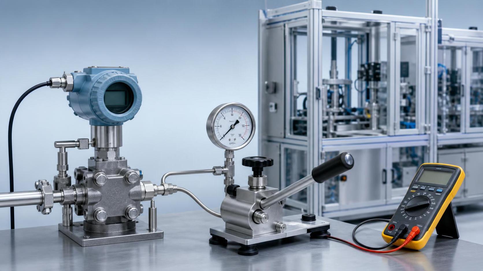
During commissioning, on-site displayed values should not be relied upon immediately. A standard meter or calibrated multimeter should be used to measure loop current. If the sensor-side output is normal but the PLC display is abnormal, the issue may lie in the analog module range configuration, program conversion formula, grounding method, or communication display link.
For level sensors with LED or LCD digital displays, LED displays are generally more visible and intuitive in bright environments, while LCD displays are suitable for applications requiring the reading of more parameters or lower power consumption. Actual selection should still prioritize protection rating, display position, ambient temperature, and maintenance convenience rather than comparing display types alone.
Recommended actions for maintaining long-term stability in high-precision level measurement
Low-error level sensors can meet high-precision requirements, provided that the accuracy grade, range, wetted material, installation method, and control system accuracy are properly matched. For demanding projects, the allowable absolute error, such as ±2 mm, ±5 mm, or ±10 mm, should be clearly defined first, and the appropriate range and product structure should then be determined accordingly.
Before procurement, it is recommended to compile medium parameters, level range, vessel pressure, temperature, installation interface, output signal, explosion-proof requirements, and on-site interference conditions. Complete operating-condition information helps technical personnel determine whether hydrostatic, differential-pressure, flush-diaphragm, or corrosion-resistant level sensors are suitable and provide more reliable configuration recommendations.
During use, a regular inspection and calibration mechanism should be established, focusing on probe deposits, vented cables, junction box sealing, output current, and zero-point condition. For critical storage tanks, an on-site comparison calibration can be performed every 6 months, and the maintenance interval can be adjusted according to continuous operating data.
When evaluating high-precision, corrosion-resistant, vibration-resistant, or 24V-powered level sensor solutions, specific medium, range, temperature, pressure, and installation conditions can be provided to Xi'an Shenghongchuang Instrumentation Co., Ltd. Professional technical personnel can then perform model selection verification, parameter confirmation, and configuration of supporting measurement and control solutions.