News Center
—— NEWS CENTER ——
Xi'an Shenghongchuang Instrument Co., Ltd.
Contact: Mr. Zhang
Mobile: 15529283736
Email: shc-sensor@qq.com
Address: Fortune Building, Sanqiao Street, Xixian New Area, Xi'an, Shaanxi Province
Basic Wiring Logic for 24V-Powered Level Sensors
24V-powered level sensors are commonly used in water tanks, storage tanks, chemical containers, wastewater treatment equipment, and automated production lines. The key to wiring is first confirming the power supply method and then identifying the output signal type. Common field models include two-wire 4-20mA, three-wire 4-20mA, three-wire 0-10V, RS485 communication types, and level sensors with relay switching outputs. Terminal definitions for different configurations are not interchangeable. Before wiring, refer to the product nameplate, manual, and wiring markings.
Industrial sites typically use a DC24V regulated power supply, with an allowable fluctuation range generally from 18V to 30V; however, the specific range should still be verified against product parameters. The positive terminal is generally marked “+24V”, “V+”, or “PWR+”, while the negative terminal is generally marked “0V”, “V-”, or “GND”. Reversing the positive and negative terminals may prevent ordinary products from operating, and models without reverse-polarity protection may also suffer internal circuit damage.
Before wiring, disconnect the main power supply of the control cabinet and use a multimeter to confirm the actual output of the 24V power supply. Excessive no-load voltage, excessive ripple, or sharing a power supply with high-power loads may cause fluctuating level readings, signal drift, or even communication interruption. For level measurement and control systems requiring high measurement accuracy, it is recommended to use an independent branch circuit for the sensor loop and install an appropriate fuse or miniature circuit breaker protection device on the power supply side.
For highly corrosive, high-temperature, high-pressure, or flammable and explosive media, wiring is only one part of the installation process. Probe material, process connection type, protection rating, explosion-proof requirements, and pressure rating must also be confirmed. For example, in strong alkaline storage tank applications, the wetted material should first be verified for compatibility with the medium concentration and temperature; it must not be selected solely based on a “corrosion-resistant” description.
Common Wiring Methods for 24V Level Sensors
Two-Wire 4-20mA Level Sensors
Two-wire 4-20mA level sensors use the same loop for power supply and signal transmission, making them commonly used in industrial applications requiring long-distance transmission and high interference resistance. Typically, the DC24V positive terminal is connected to the sensor “+” terminal, the sensor “-” terminal is connected to the control instrument, current input module, or PLC analog input terminal, and the instrument negative terminal is then connected back to the power supply 0V to form a complete current loop.
In this type of loop, 4mA usually corresponds to the lower range limit, and 20mA corresponds to the upper range limit. For a range of 0 to 5m, for example, 12mA theoretically corresponds to a level of approximately 2.5m. If the actual level is stable but the instrument continuously displays a low or high reading, check the range setting, supply voltage, loop resistance, and input type of the control instrument rather than directly concluding that the sensor has failed.
When connecting to a PLC, confirm whether the analog module is an active-input or passive-input type. An active-input module can provide loop power to a two-wire transmitter itself; connecting an external 24V power supply as well may result in duplicate power supply. A passive-input module requires an external 24V power supply to establish the loop. Loop drawings should be standardized during the project design stage to prevent field personnel from wiring based on experience alone.
The allowable loop load must meet the sensor technical specifications. A commonly used estimation method is: load resistance must not exceed “(supply voltage - minimum operating voltage) ÷ 0.02A”. For example, with a 24V supply and a sensor minimum operating voltage of 12V, the theoretical maximum loop load is approximately 600Ω; after allowing for a safety margin, the actual design value should be lower than this value.
Three-Wire 4-20mA and 0-10V Level Sensors
Three-wire products generally have three wires: power positive, power negative, and signal output. During wiring, the brown wire is commonly used as the DC24V positive terminal, the blue wire as 0V, and the black wire as the signal wire. However, wire colors are not fully consistent among all manufacturers, so terminal markings shall be the final reference. The signal negative terminal is generally common-grounded with power supply 0V, and the analog common terminal of the control instrument must also be connected correctly.
For three-wire 4-20mA models, connect the signal wire to the current input terminal of the instrument or PLC, and connect the instrument common terminal to 0V. For 0-10V models, the signal wire must be connected to a voltage input terminal. Incorrectly connecting it to a current input terminal will cause abnormal readings and may damage the input module in serious cases. The output method should be clearly specified during procurement; it is not sufficient to state only “24V level sensor”.
0-10V signals are relatively sensitive to line voltage drop and common grounding conditions, so the distance between the sensor and acquisition module should be controlled. In general industrial environments, when the signal cable exceeds 30m, cable size, electromagnetic environment, and grounding scheme should be carefully evaluated. For longer distances or strong frequency-converter interference, a 4-20mA output is generally more favorable for maintaining signal stability.
If a level sensor has a local LED or LCD display, the display is only used for on-site readings and parameter viewing and does not change the analog wiring principles. LEDs are easier to read under strong light, while LCDs can display more values and menu information. However, the choice between them should be based on site illumination, viewing distance, ambient temperature, and maintenance requirements, rather than product performance being judged solely by display type.
Stability Control for Shielding, Grounding, and Cable Routing
Signal Cables Should Be Kept Away from High-Power Lines and Interference Sources
Shielded twisted-pair cable is recommended for level sensor signal lines, particularly for 4-20mA, 0-10V, and RS485 communication circuits. Signal cables should not be routed in parallel for long distances in the same tray as 380V power lines, frequency-converter output cables, or motor cables. Where this cannot be avoided, maintain a spacing of at least 200mm and use perpendicular crossings wherever possible.
The shield layer is generally recommended to be grounded at one end only, usually connected to a reliable protective earth at the control cabinet side, while the field sensor side is left floating and properly insulated. Grounding at both ends may create ground loop currents where different ground potentials exist, causing signal fluctuations. Special explosion-proof, communication, or system grounding requirements shall be implemented according to project electrical specifications rather than relying on a single general practice.
Wiring terminals should be firmly crimped, and conductor copper cores should not be exposed excessively. Flexible bend-resistant cables should be used near vibrating equipment, and sufficient bending allowance should be reserved at the sensor cable outlet to prevent long-term cable tension. When selecting vibration-resistant level sensors, attention should also be paid to the mounting structure, process connection rigidity, and probe natural frequency. Simply increasing cable fixing cannot resolve measurement errors caused by mechanical vibration.
Within the control cabinet, the 24V power supply, analog modules, isolators, and terminal blocks should be clearly separated by area. For high-accuracy level measurement systems, signal isolators or isolated analog modules may be used to reduce the effects of ground potential differences and common-mode interference. A high sensor accuracy class does not necessarily mean that total system error will be low; installation position, medium fluctuations, temperature changes, and instrument conversion all affect the final result.
Inspection Methods After Connection to Control Instruments and PLCs
Step-by-Step Verification Before and After Power-On
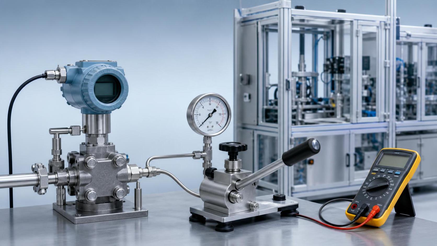
After completing the wiring, first check whether terminals are loose, whether positive and negative terminals are correct, and whether the shielding layer has been incorrectly connected to a signal terminal before energizing the system. After power-on, use a multimeter to measure the voltage at the sensor power terminals and confirm that it remains within the rated operating range under load. For two-wire 4-20mA products, measure loop current in series; do not connect a multimeter directly in parallel with the current loop.
The control instrument or PLC program should be configured with an input type and range consistent with the sensor. For example, if the sensor range is 0 to 10m and the output is 4-20mA, set the engineering value lower limit to 0 and upper limit to 10. If the instrument is incorrectly configured for 0-20mA, the zero point will have an obvious 20% deviation. Alarm values should also be set according to the safety margin of the storage tank and must not rely solely on full-scale values.
During commissioning, it is recommended to compare at least three level points, such as low level, mid-level, and a position close to full scale. If the deviation between measurement points and a standard ruler or calibrated instrument follows a linear pattern, first check range conversion. If readings fluctuate irregularly, investigate power supply ripple, grounding, interference, medium foam, probe installation position, and mechanical vibration.
When sanitary flush-diaphragm level sensors are used in food, pharmaceutical, or viscous media applications, also check whether the diaphragm is covered by residues and whether the cleaning process damages the sensing surface. Under strong alkaline conditions, verify the compatibility of wetted materials such as 316L, stainless steel, PTFE, and ceramics with the actual concentration, temperature, and cleaning cycle. Corrosion resistance must be assessed under specific medium conditions.
Selection Confirmation Checklist Before Wiring Level Sensors
Parameter Matching Determines Long-Term Operating Reliability
Before wiring, confirm the level sensor range, supply voltage, output signal, accuracy, installation method, process pressure, medium temperature, and protection rating. Measurement principles and installation requirements differ between ordinary water tanks and closed pressure vessels. Field wiring and commissioning priorities also vary among submersible, hydrostatic, radar, ultrasonic, and capacitive level sensors.
For high-accuracy requirements, it is recommended to define the allowable total system error rather than focusing only on the sensor’s nominal accuracy. For example, a sensor accuracy of 0.25%FS theoretically corresponds to an error of approximately ±25mm over a 10m range. When installation height error, instrument error, and temperature drift are added, the final operating error may exceed the nominal value of the individual sensor. Therefore, level sensors with low error are suitable for high-accuracy requirements, but require complete system coordination.
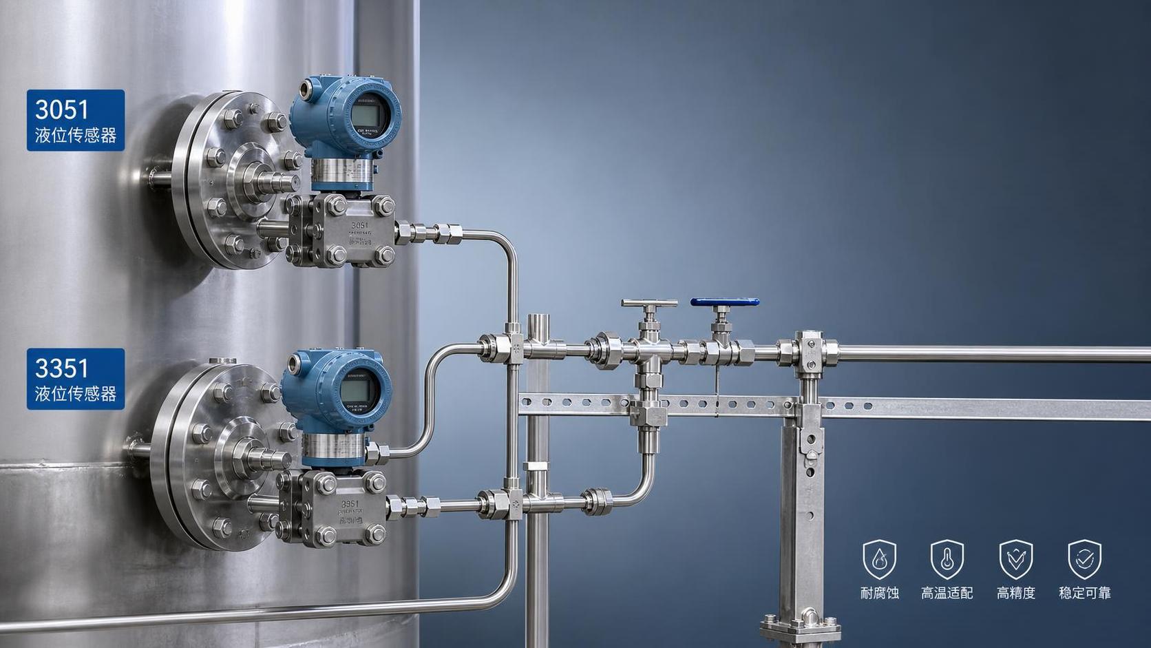
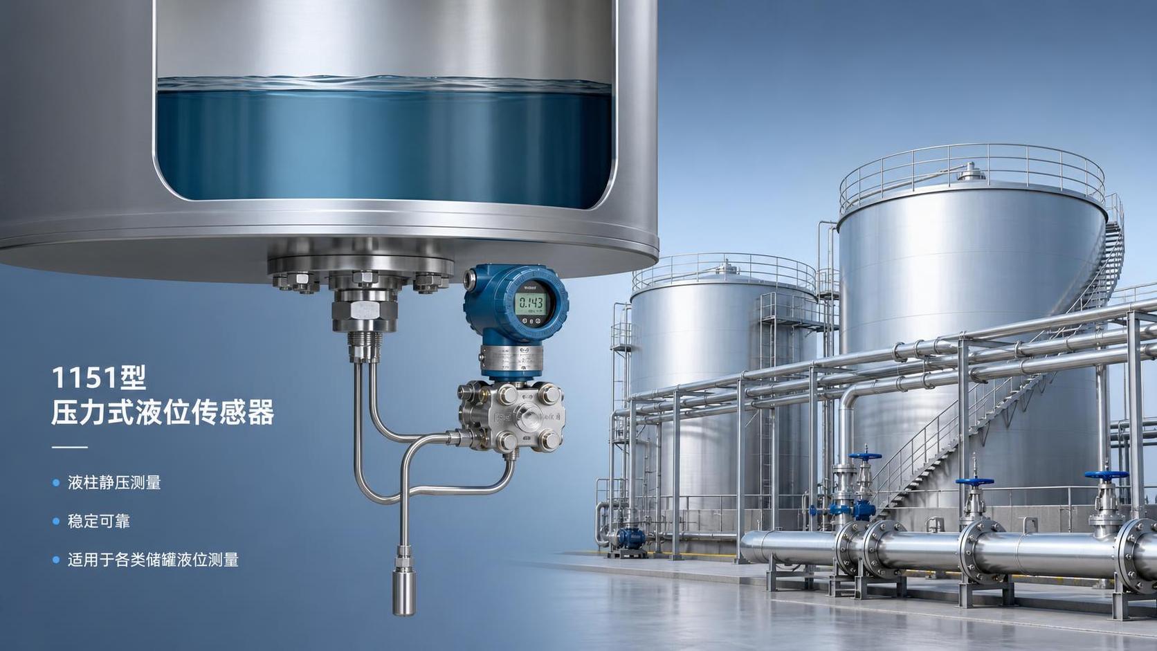
For level measurement solutions involving 3051, 3351, or 1151 series products, focus on comparing sensor principles, diaphragm materials, applicable hydrostatic pressure range, communication protocols, process connections, and maintenance costs. Price ranges for different series are affected by range, accuracy, material, explosion-proof rating, display function, and customization requirements. Procurement comparisons should be made based on complete technical specification sheets using consistent criteria.
Xi'an Shenghongchuang Instrumentation Co., Ltd. can provide selection recommendations for level sensors, matching transmitters, and intelligent digital display control instruments based on medium characteristics, tank dimensions, control system interfaces, and site conditions. Before project implementation, please provide the power supply method, output requirements, range, temperature and pressure, medium composition, and installation drawings. Installation and commissioning should be carried out after technical personnel confirm the wiring scheme and product configuration.