


News Center
—— NEWS CENTER ——
Xi'an Shenghongchuang Instrument Co., Ltd.
Contact: Mr. Zhang
Mobile: 15529283736
Email: shc-sensor@qq.com
Address: Fortune Building, Sanqiao Street, Xixian New Area, Xi'an, Shaanxi Province
When purchasing an ambient-temperature pressure transmitter, how do you confirm the measuring range, output signal, and connections? This article outlines the key selection criteria to help purchasing personnel reduce the risk of choosing an incompatible product.
1. Define the operating conditions before specifying the purchase parameters
Identify the measured medium and operating conditions
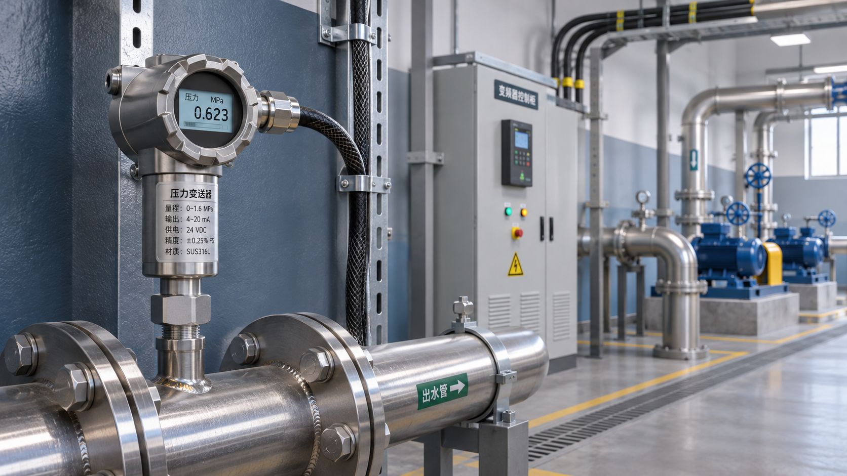
Ambient-temperature pressure transmitters are commonly used in water supply, pneumatic and hydraulic systems, and equipment integration. When making a purchase, do not simply specify “water pressure” or “air pressure.” Also provide the medium, normal operating pressure, maximum pressure, and installation location so the supplier can determine whether the instrument is suitable for the actual operating conditions.
Ambient temperature does not mean that the temperature is the same at every location. Confirm both the medium temperature at the transmitter installation point and the ambient temperature, and consider temperature changes during equipment startup, shutdown, and cleaning. If steam or brief periods of high temperature are involved, tell the supplier the duration and maximum temperature.
Whether the medium is corrosive, contains particles, is viscous, or tends to crystallize can also affect product selection. Wetted materials must be confirmed based on the medium’s composition, concentration, and temperature; long-term compatibility cannot be determined solely from descriptions such as “for water” or “stainless steel.”
Distinguish between pressure reference types
Gauge pressure is referenced to local atmospheric pressure and is commonly used in closed pipelines and water supply equipment. Absolute pressure is referenced to a perfect vacuum and is suitable for measurements where the effect of changes in atmospheric pressure must be excluded. Since the two use different reference points, specify the required type on the purchase order.
For negative-pressure or vacuum measurements, specify the pressure range and reference type. For example, a gauge pressure range of -0.1 to 0 MPa is not directly equivalent to an absolute pressure range of 0 to 0.1 MPa.
If the application involves both positive and negative pressure, provide the complete minimum and maximum pressure values so the supplier can confirm whether a compound positive/negative pressure range and corresponding calibration method are required.
2. Selecting the range: Cover normal values and account for peaks
Consider operating pressure and pressure fluctuations
The range should cover the equipment’s actual operating range and allow an appropriate margin. For systems with relatively stable pressure, using a normal operating pressure of approximately 60%–80% of full scale as an initial reference for discussion can be helpful. Finalize the range based on actual site fluctuations and the manufacturer’s recommendations.
For example, if a pipeline normally operates at approximately 0.6 MPa and pressure is relatively stable, you could discuss a 0–1 MPa range with the supplier. If significant water hammer occurs during startup or shutdown, selecting a range based only on normal pressure may damage the sensor.
The range should not be increased indiscriminately. Since error is expressed as a percentage of full scale, the corresponding pressure error typically increases as the range is extended. Peak-pressure protection and measurement requirements at the low end must therefore both be considered.
Check overload capacity and accuracy separately
Overpressure is the pressure a product can withstand under specified conditions. It is not the pressure at which the product can operate continuously, nor does it mean that the output will remain accurate beyond the measuring range. For applications involving frequent pressure surges, provide the measured peak pressure, frequency, and duration.
Accuracy is usually calculated as a percentage of full scale. For example, if a model has a combined error of ±0.5% FS and a range of 0–1 MPa, the corresponding error limit is approximately ±0.005 MPa. Actual acceptance testing should follow the conditions specified in the product’s technical documentation.
The following example is provided to help organize purchasing information. The final range must still be confirmed based on peak pressure, accuracy, and the specific product.
3. Confirming the output signal: Work backward from the receiving device
Check the controller input and power supply
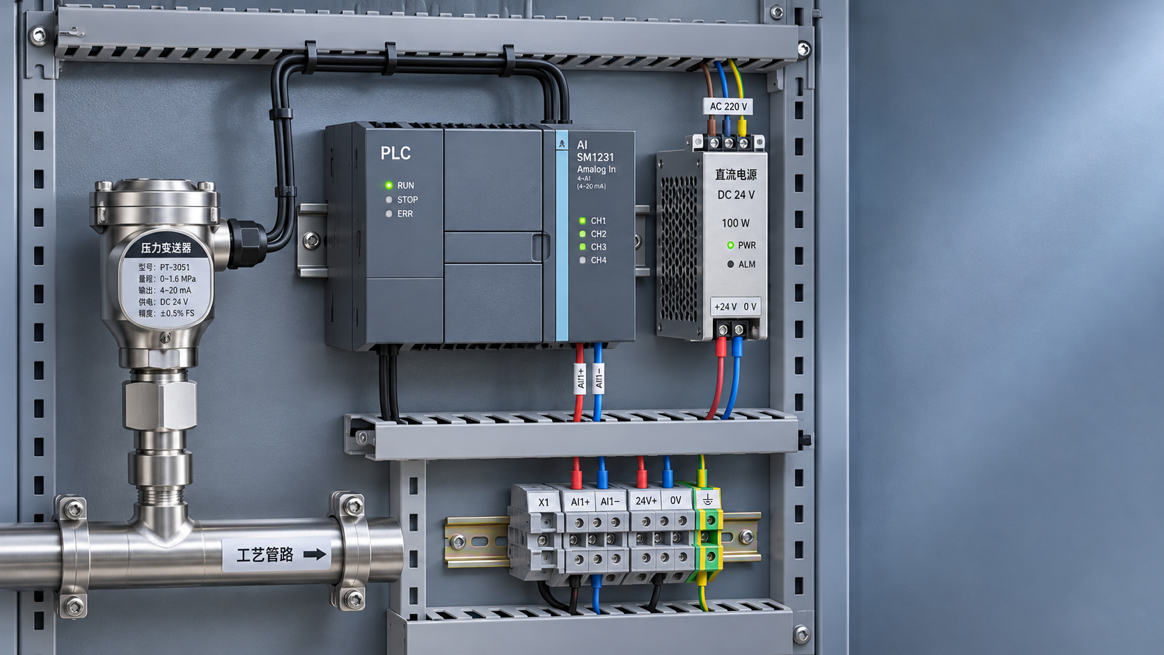
First check the input type of the PLC, digital display meter, or data acquisition module, and then select the transmitter output. Common analog signals include 4–20 mA current and 0–5 V or 0–10 V voltage signals. If the input channel is incompatible, simply changing the displayed range will not resolve the issue.
4–20 mA signals are commonly used for long-distance transmission in industrial environments, but the loop power supply, cable resistance, and receiver load must still be checked. Voltage signal wiring and acquisition methods must meet the equipment requirements. For longer cable runs, also consider voltage drop and interference.
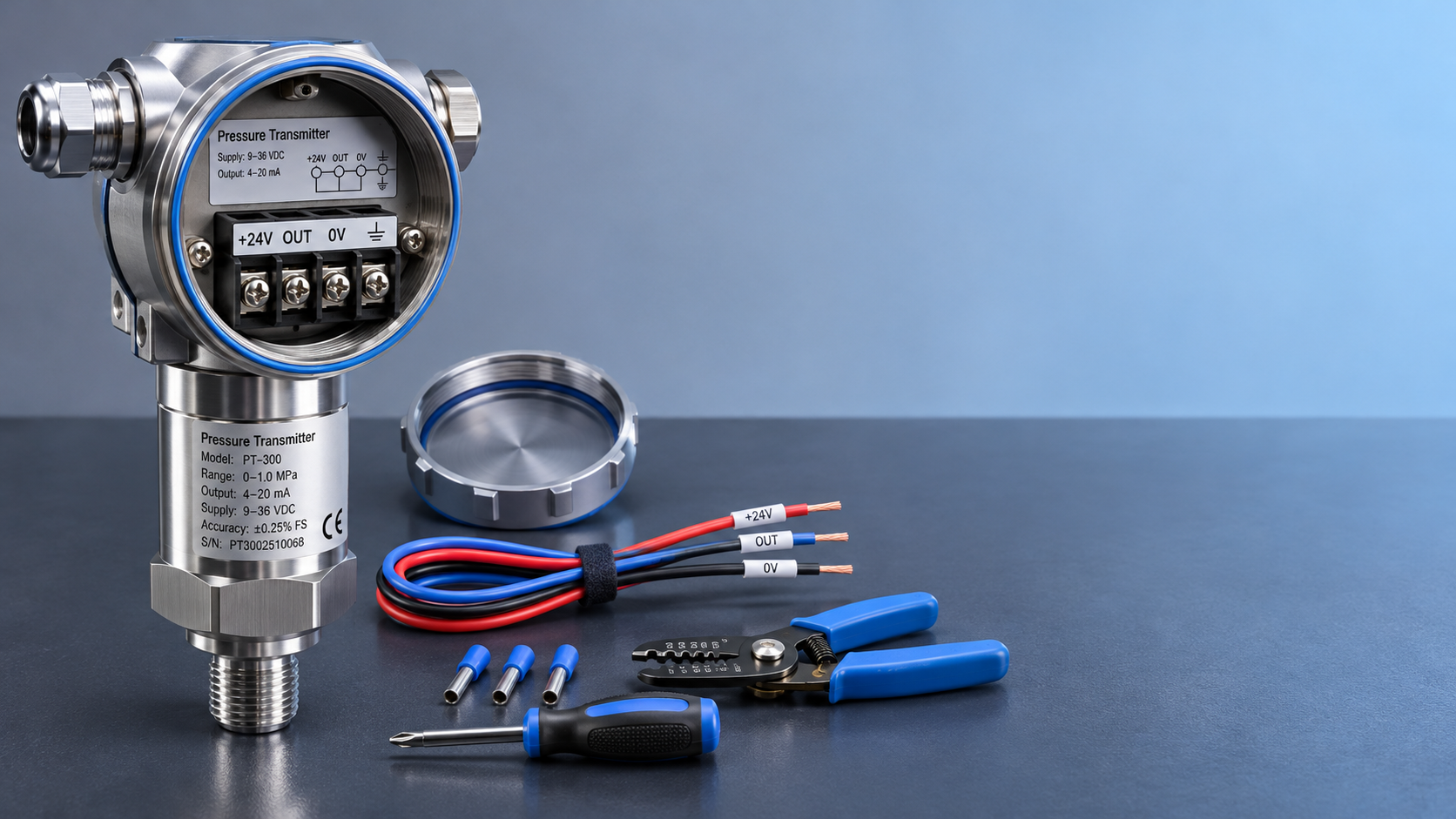
When confirming whether the transmitter is two-wire or three-wire, also request the wiring diagram and power supply range. Do not treat “24 V power supply” as complete wiring information; check the power polarity, signal terminals, and wiring method for the controller channel as well.
Define display and control requirements
If a local reading is required, confirm in advance whether a display is included, the display units, and the mounting orientation. For remote monitoring, verify that the control system can convert the signal into engineering units based on the actual range.
For alarms or interlocks, specify whether the controller will process the analog signal or whether the instrument must provide a switching output. The switching type, setting method, and load capacity must also be confirmed separately.
For example, with a 0–1 MPa range corresponding to 4–20 mA, 0.5 MPa corresponds to 12 mA under linear conversion. After connection, set the same lower and upper limits in the controller and verify them on site.
4. Confirming the connections: Specify mechanical and electrical connections separately
Verify the thread, sealing method, and installation space
For the pressure connection, confirm at minimum the thread specification, male or female thread, and sealing method. Specifications such as M20×1.5 and G1/4 are not interchangeable simply because their outside diameters are similar. If the original equipment documentation is incomplete, provide the supplier with connection drawings, photos of the actual part, and key dimensions for verification.
Sealing may rely on an end face, a gasket, or another design; confirm the method based on the connection design. Also check the installation space, access for a wrench, and whether an adapter or isolator is required.
Specify the electrical connection separately, such as a cable, aviation plug, or DIN connector, and check the cable length, ingress protection rating, and site moisture conditions. Confirm the rating against the product documentation for the selected connection configuration and correct installation conditions.
Check available configurations against the product documentation
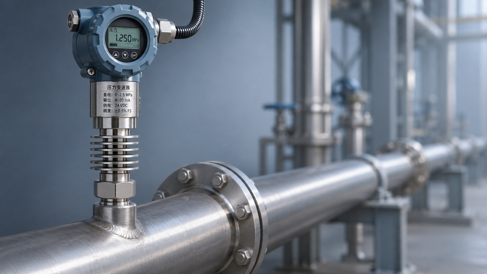
For example, the documentation for the JSCW-308GY Domestic High-Temperature Pressure Transmitter, Diffused Silicon 2088 Pressure Sensor lists multiple ranges, signals, and connection options, which can be used to discuss the specific configuration with the supplier. The product documentation specifies a medium temperature range of -30 to +85℃. Even though “high-temperature” appears in the product name, the actual temperature range and confirmed configuration should be used as the basis for selection.
The pressure connections listed in its documentation include M20×1.5, M12×1, G1/4, and G1/2 male threads, among others. Outputs include 4–20 mA and several voltage signals. Not all options are supplied together as standard, so confirm the required combination and supply specification before placing an order.
The product documentation also lists 304 or 316 stainless steel for wetted parts. For corrosive media, provide the supplier with the medium’s composition, concentration, and temperature, and ask them to confirm the actual wetted components and suitability.
5. Finalize the checklist and acceptance requirements before ordering
Turn verbal requirements into verifiable specifications
A practical purchase checklist should include the medium, pressure reference type, range, normal and maximum pressure, medium and ambient temperatures, accuracy requirement, output signal, power supply method, pressure connection, electrical connection, and quantity.
For applications involving moisture, vibration, pressure surges, or special media, provide the site conditions and installation photos. For special requirements such as explosion protection, specify the applicable area and required certificates, and have the supplier verify whether the corresponding model meets the requirements.
During acceptance, check the nameplate, range, connections, and wiring diagram, and agree on calibration records, inspection documents, and sampling methods according to project requirements. After installation, check the zero point, signal direction, and controller reading to avoid cases where the specifications are correct but the wiring or configuration is not.
When preparing to purchase, compile the operating-condition and connection information above and submit it to Xi'an Shenghongchuang Instrumentation Co., Ltd. Confirm the range, output, materials, and delivery configuration item by item, then place the order based on the written quotation and technical documentation.
Related Recommendations
 Unstable Signals Near a Variable Frequency Drive? Key Selection Considerations for an EMI-Resistant Pressure Transmitter
 How to wire a 24 VDC pressure transmitter: two-wire vs. three-wire configurations
 How to Calculate Power and Signal Compatibility When Connecting a 24 V Pressure Transmitter to a PLC
 Heat-Dissipating Pressure Transmitters vs. Isolation and Cooling Solutions: How to Choose for High-Temperature Pressure Measurement