


News Center
—— NEWS CENTER ——
Xi'an Shenghongchuang Instrument Co., Ltd.
Contact: Mr. Zhang
Mobile: 15529283736
Email: shc-sensor@qq.com
Address: Fortune Building, Sanqiao Street, Xixian New Area, Xi'an, Shaanxi Province
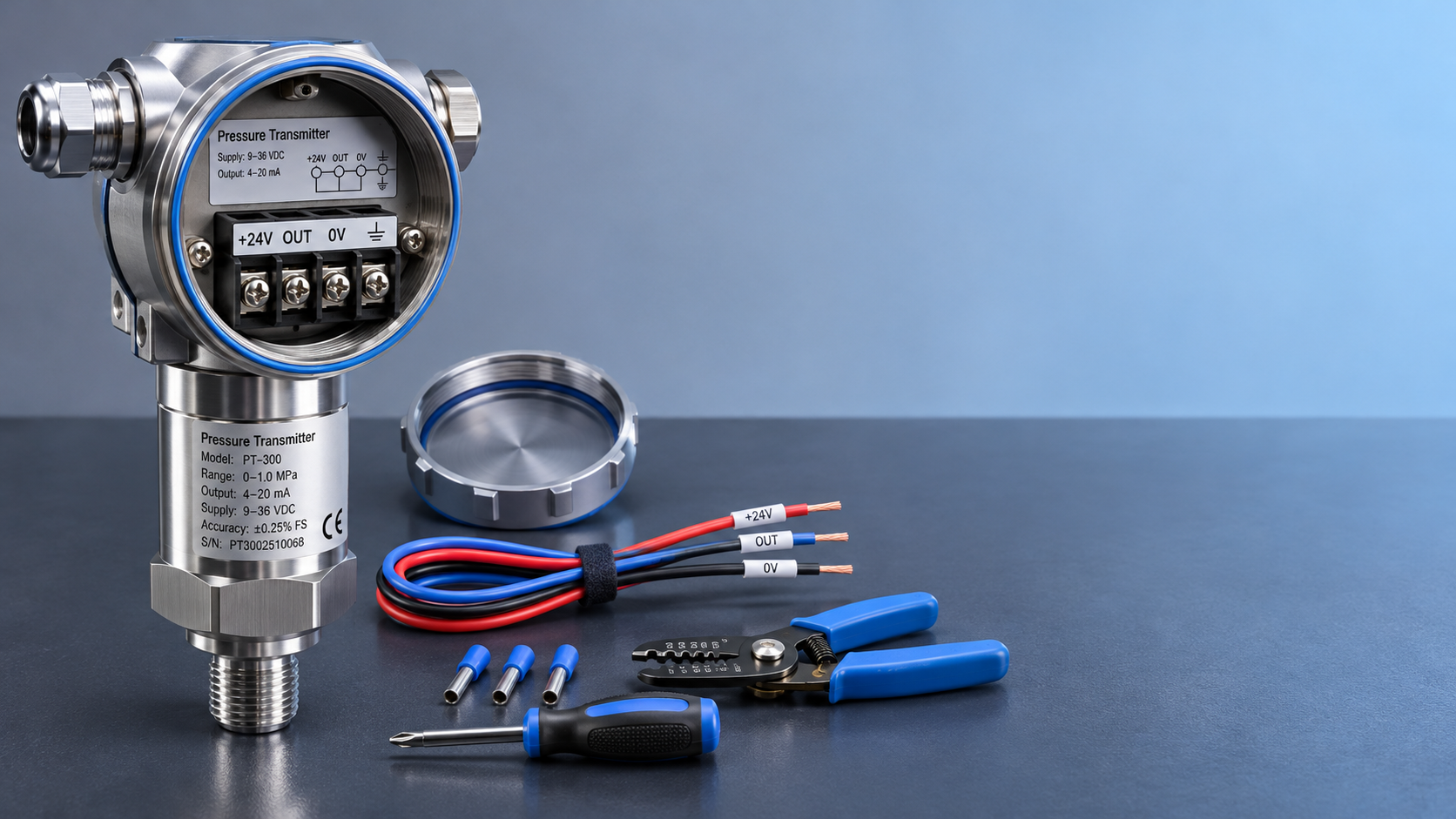
How should a 24VDC pressure transmitter be wired correctly? This article compares two-wire and three-wire wiring methods to help operators identify wiring terminals and avoid incorrect connections.
I. Confirm the Power Supply and Output Signal Before Wiring
24VDC indicates that the transmitter uses a DC power supply, but the supply voltage alone does not determine the wiring method. Before wiring, check the product nameplate, terminal markings, and manual to confirm whether the device is two-wire or three-wire, and whether its output is a current or voltage signal.
Two-wire pressure transmitters commonly have a 4–20mA output, with the power supply and signal sharing two wires. Three-wire transmitters typically have a power positive terminal, a power negative terminal, and a signal output terminal. Common voltage outputs include 0–5V and 0–10V. Refer to the actual product for the specific terminal definitions.
Also check the input type of the PLC, digital display instrument, or acquisition module. Do not wire a current input terminal as though it were a voltage input. Some instruments allow the input mode to be switched, but the terminal locations and parameter settings must also be checked.
II. Wiring a Two-Wire Pressure Transmitter
1. Identify the Positive and Negative Terminals in the Loop
Two-wire 4–20mA transmitters are typically marked with positive and negative power terminals, commonly shown as “+” and “-” or “SUPPLY+” and “SUPPLY-”. The negative terminal also carries the return loop current and should not be treated simply as a separate voltage signal wire.
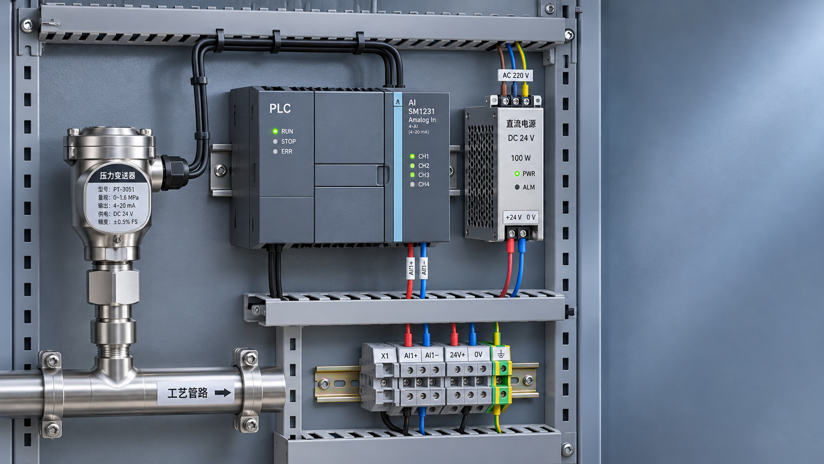
When using a passive current input module, one common wiring method is to connect the 24V power supply positive terminal to the transmitter positive terminal, the transmitter negative terminal to the PLC or instrument current input positive terminal, and the current input negative terminal to the power supply negative terminal, forming a closed series loop.
The wiring can be represented as: 24V+ → transmitter+ → transmitter- → current input+ → current input- → 24V-. Terminal names may vary between devices; check the input module manual for the correct wiring.
2. Check the Input Channel's Power Supply Method
Some PLC or instrument current input channels provide loop power and are therefore active inputs. In this case, connect the transmitter according to the channel's wiring method for two-wire transmitters. Do not add an external 24V power supply in series without first confirming that it is appropriate, as this may cause a power supply conflict or damage the equipment.
The 4–20mA signal corresponds to the lower and upper limits of the range configured in the instrument. For example, for a range of 0–1MPa, ideally 4mA corresponds to 0MPa, 12mA to 0.5MPa, and 20mA to 1MPa. The actual display is also affected by transmitter accuracy and system settings.
The loop must also provide sufficient operating voltage for the transmitter. After accounting for voltage drops across the input module, cables, and other devices in series, the voltage across the transmitter must still be within its specified range.
III. Wiring a Three-Wire Pressure Transmitter
1. Connect the Power and Signal Wires
Three-wire products generally have a power positive terminal, a power negative terminal, and a signal output terminal, commonly marked “V+”, “GND”, and “OUT”. The power negative terminal is usually also the signal reference, but always follow the manufacturer's wiring diagram.
For a common-ground 0–10V output, for example, connect the 24V power supply positive terminal to V+, the power supply negative terminal to GND, and OUT to the PLC voltage input positive terminal. Connect the PLC voltage input common terminal to the transmitter GND. Before connecting, confirm that the PLC input common terminal supports this wiring method.
After powering on, configure the PLC for the same voltage input range as the transmitter and set the corresponding pressure limits. If the transmitter output is 0–5V but the channel is configured to scale for 0–10V, the displayed value will have a scaling error.
2. Check Common Grounding and Input Compatibility
Three-wire voltage outputs are sensitive to the signal reference point. If the receiving device and transmitter use different power supplies, or if there are common-ground restrictions across multiple channels, first check the input module's isolation method and common terminal wiring. Use a suitable isolation device if necessary.
Do not connect the three-wire OUT terminal directly to the 24V power supply positive terminal, and do not determine polarity based solely on wire color. Pin assignments or wire colors for aviation connectors, DIN connectors, and cable outlets may vary by model, batch, and customization requirements.
The following compares two common wiring methods; it does not replace the wiring diagram for the specific device:
IV. Check the Wiring Against the Product Specifications
Both the output specifications and wiring method must be considered when selecting a product and wiring it. Products in the same series may be available with different signal versions, so do not reuse the wiring method for another device simply because it looks similar.
For example, the AE-T General-Purpose Domestic Diffused Silicon Negative Pressure Pressure Sensor is available with multiple ranges and output options and can be used in applications such as hydraulic systems, pneumatic systems, and constant-pressure water supply. Refer to the ordered version and the documentation supplied with the product for the specific power supply and wiring method.
The table below lists common specifications available for this series. During installation, also check the pressure connection, media compatibility, and operating temperature at the installation site to avoid electrical compatibility without application compatibility.
V. Power-On Checks and Troubleshooting Common Issues
1. Inspection Sequence Before and After Powering On
Before wiring, disconnect the power supply. Confirm that the equipment at the installation site has been depressurized or is in a safe condition for the work, then check the terminals, wire insulation, and tightness of connections. Do not remove the transmitter while pressure conditions are unknown or the equipment is energized.
After powering on, use a multimeter on an appropriate range to check the voltage at the transmitter power terminals. Connect the meter in parallel to measure voltage. To measure loop current, break the loop and connect the ammeter in series. Confirm that the meter's socket and range are correct; never connect the meter on its current range directly across the power supply terminals.
Check the PLC input type, engineering-unit limits, and units, then verify the reading at a known pressure point under safe conditions. For negative-pressure measurement, also confirm the range direction and display sign; do not apply a positive-pressure range without adjustment.
2. How to Handle Abnormal Readings
If there is no signal, first check the power supply, polarity, loose terminals, and whether the loop is open. For two-wire transmitters, also confirm that the input channel provides loop power and that the voltage drop in the loop is not excessive.
If the reading is low or the scaling is incorrect, check that the transmitter output range matches the PLC input settings and that the pressure limits are configured correctly. For three-wire transmitters, also check the signal common connection to avoid inconsistent reference points.
If the reading fluctuates, check the cable shielding and grounding method, and keep signal cables away from interference sources such as inverter power cables where possible. Ground the shield in accordance with the equipment and site requirements. If the issue persists after these checks, record the model, supply voltage, output type, and photos of the site wiring, then contact the technical staff at Xi'an Shenghongchuang Instrumentation Co., Ltd. for assistance.
Related Recommendations
 Unstable Signals Near a Variable Frequency Drive? Key Selection Considerations for an EMI-Resistant Pressure Transmitter
 How to wire a 24 VDC pressure transmitter: two-wire vs. three-wire configurations
 How to Calculate Power and Signal Compatibility When Connecting a 24 V Pressure Transmitter to a PLC
 Heat-Dissipating Pressure Transmitters vs. Isolation and Cooling Solutions: How to Choose for High-Temperature Pressure Measurement