


News Center
—— NEWS CENTER ——
Xi'an Shenghongchuang Instrument Co., Ltd.
Contact: Mr. Zhang
Mobile: 15529283736
Email: shc-sensor@qq.com
Address: Fortune Building, Sanqiao Street, Xixian New Area, Xi'an, Shaanxi Province
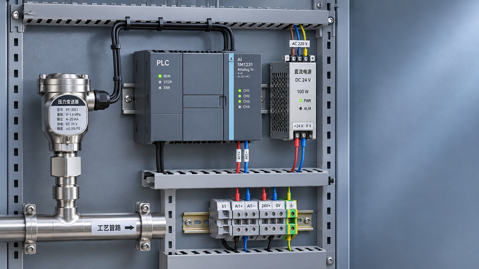
Before connecting a 24V-powered pressure transmitter to a PLC, the project manager should calculate the available power-supply capacity, loop load, and signal type to prevent compatibility issues from delaying commissioning. “24V” usually refers to the nominal DC voltage; it does not mean that every transmitter can be connected directly to any PLC analog input channel. The power-supply method, output type, and wiring configuration must be verified against the product manual, item by item.
I. First Confirm the Basic Power and Signal Requirements
1. Distinguish Between Supply Voltage and Output Signal
Common pressure transmitter outputs include 4–20mA, 0–10V, 0–5V, and RS485 communication. 24VDC is the power-supply requirement, while 4–20mA or 0–10V is the signal format used to transmit pressure information. The two must not be confused.
When checking the transmitter nameplate, record the permitted supply-voltage range, maximum operating current, output type, and wiring diagram. When reviewing the PLC documentation, confirm the signal ranges supported by the analog input channel, input impedance, channel isolation method, and permitted common-mode voltage.
For example, if a PLC channel supports only 0–10V input but the transmitter outputs 4–20mA, they cannot simply be wired as if they used the same signal type. Use a compatible current-input module, or, after performing the necessary calculations, an appropriate signal converter.
II. Calculate 24V Power-Supply Capacity and Voltage Margin
2. Calculate Power-Supply Capacity Based on Maximum Current
For a centralized power supply, add the maximum operating currents of the transmitters, isolators, and other shared devices, then allow for startup current, power-supply derating, and an appropriate margin. Do not estimate the power supply’s rated current based only on the pressure transmitters’ normal readings.
For example, if the maximum loop current for each of eight two-wire transmitters is estimated at 22mA, the combined loop current is 176mA. If the maximum current of the other devices totals 500mA, the total load is 676mA. With an initial reserve margin of 25%, the power supply should have a rated current of at least approximately 845mA. Final selection should also account for temperature derating and startup characteristics.
The 22mA figure here is only an example for calculation. The actual maximum current should be based on the device’s fault output and technical documentation. When multiple devices share a power supply, also check branch protection and wiring ampacity to prevent a fault on one branch from affecting the entire system.
The Minimum Voltage Also Needs to Be Checked
24V is a nominal value. Power-supply tolerance, line resistance, and protective components all affect the voltage at the device. Calculations should use the lowest possible power-supply output voltage, rather than assuming an ideal 24V at all times.
For a two-wire current loop, ensure that the minimum supply voltage is no less than the sum of the transmitter’s minimum operating voltage and the maximum voltage drops across all components. These drops include those across the PLC input, cable, isolator, and other devices in series. If the module documentation specifies a fixed voltage drop, calculate accordingly.
For example, if the minimum supply voltage is 22V, the transmitter’s minimum operating voltage is 12V, the PLC input resistance is 250Ω, and the round-trip cable resistance is 50Ω, the total voltage drop across the resistances is 6.6V at 22mA. The transmitter would then have approximately 15.4V, which is 3.4V above its minimum requirement. If there are additional devices in series, their voltage drops must also be deducted.
III. Check Wiring and Range According to Signal Type
3. Two-Wire and Three-Wire Devices Require Different Wiring
Two-wire 4–20mA transmitters are typically powered through the signal loop. Before connecting one, confirm whether the PLC current input is active or passive, and whether the module can supply power to the field device. If both ends supply power, or neither provides loop power, wiring errors or abnormal signals may result.
Three-wire transmitters generally have a positive power terminal, a common terminal, and a signal output terminal, but the specific terminal definitions must still be confirmed against the manufacturer’s wiring diagram. Before connecting the transmitter to a PLC, verify the permitted common-terminal connection method and ensure that the voltage or current output matches the channel configuration.
For voltage outputs, also check the PLC input impedance, the transmitter’s permissible load, and the cable distance. Over long distances or in environments with strong interference, voltage signals are more susceptible to line voltage drops and potential differences. Whether to switch to a current signal should be determined based on site conditions and equipment specifications.
IV. Complete On-Site Commissioning and Troubleshooting
4. Verify the System Step by Step, from Power Supply to PLC Display
Before powering on, disconnect the power and check polarity, terminal numbers, and shield connections. Confirm that the wiring matches the diagrams for the transmitter and PLC module. After powering on, measure the power-supply output and the actual voltage at the transmitter. If it is safe to do so, check the loop current as well.
During commissioning, use a calibrated signal source or standard pressure equipment to check the low, midpoint, and high points of the range. For a 0–1MPa range with a 4–20mA output, for example, the theoretical values are 4mA at 0MPa, 12mA at 0.5MPa, and 20mA at 1MPa. Actual error should also be assessed in light of the equipment accuracy and site conditions.
If the PLC reading is unstable, troubleshoot in sequence: power-supply ripple, loose wiring, shield grounding, separation of power and signal wiring, and parameter filter settings. Shielding and grounding must follow the equipment manual and site electrical design; do not make connections based solely on experience.
Check the Interfaces of Other Sensors in the Same Cabinet
A control cabinet may collect both pressure and weighing signals, but similar sensor names do not mean their interfaces are the same. A load cell typically requires a matching excitation supply and weighing instrument or acquisition module; it must not be handled using the same wiring method as a 24V pressure transmitter.
For example, the domestically manufactured YZC-660 miniature cantilever beam force sensor load cell can be used for batching scales and force measurement and control. The product documentation specifies an excitation voltage of 10VDC. When selecting a sensor, further confirm the specific specifications, output units, and requirements for the compatible acquisition module with the supplier. Do not apply 24V directly to the excitation terminals.
Xi’an Shenghongchuang Instrumentation Co., Ltd. provides sales and technical services for sensors, transmitters, and supporting instruments. For project selection, compile the pressure range, transmitter model, PLC module model, supply voltage, cable length, and site operating conditions. Technical personnel can then help verify the wiring and load margin before commissioning in accordance with the confirmed plan.
Related Recommendations
 How to Calculate Power and Signal Compatibility When Connecting a 24 V Pressure Transmitter to a PLC
 Heat-Dissipating Pressure Transmitters vs. Isolation and Cooling Solutions: How to Choose for High-Temperature Pressure Measurement
 Compensation Principles and Temperature Drift Parameters of Temperature-Compensated Pressure Transmitters
 Selecting a High-Temperature Liquid Pressure Transmitter: How to Determine Temperature, Sealing, and Range