


News Center
—— NEWS CENTER ——
Xi'an Shenghongchuang Instrument Co., Ltd.
Contact: Mr. Zhang
Mobile: 15529283736
Email: shc-sensor@qq.com
Address: Fortune Building, Sanqiao Street, Xixian New Area, Xi'an, Shaanxi Province
How can a pressure transmitter with temperature compensation reduce measurement errors caused by temperature changes? This article explains the compensation principle and temperature drift parameters to support technical selection.
1. Why Temperature Affects Pressure Measurement
A pressure transmitter converts the pressure of a medium into an electrical signal, but its sensing element and electronic circuitry do not respond only to pressure. When the ambient or medium temperature changes, the characteristics of the elastic element, sensing chip, and circuit components may also change, causing the output to deviate from the actual pressure.
Take a common piezoresistive pressure sensor as an example. Pressure deforms the silicon diaphragm, changing the output of the resistive bridge. At the same time, temperature also affects resistance and the mechanical properties of the diaphragm. Therefore, the transmitter output may still drift even when the pressure remains constant.
Temperature effects usually appear in two areas: zero point and span. Zero-point drift is reflected in output changes when there is no pressure, while span drift is reflected in changes in output gain at the same pressure. Both errors may occur simultaneously and may also vary nonlinearly with temperature.
2. Basic Principles of Temperature Compensation
From Temperature Measurement to Pressure Correction
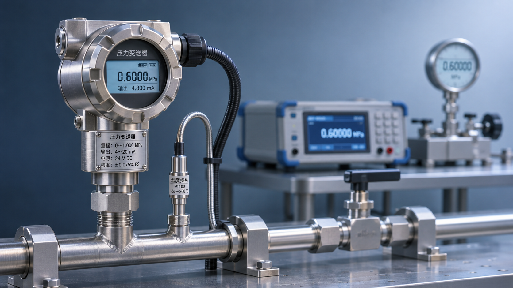
Temperature compensation generally involves measuring the temperature near the sensing element while measuring pressure, then correcting the pressure signal based on a predefined relationship between temperature and error. Here, “temperature compensation” refers to using temperature information to correct pressure measurement errors; it should not be directly interpreted as converting process variables such as flow under different temperature and pressure conditions.
During production, the manufacturer collects output data at multiple temperature and pressure points, identifies how the zero point and sensitivity vary with temperature, and then stores compensation coefficients in the circuit or digital processing unit. During operation, the transmitter uses the measured temperature to apply the corresponding coefficients and reduce temperature-induced deviations.
Compensation methods include analog compensation, such as resistor networks, and digital compensation, such as lookup tables, piecewise fitting, or polynomial calculations. Digital methods are well suited to handling more complex nonlinear relationships, but their effectiveness still depends on calibration data, temperature measurement location, and product design.
Difference Between Compensation Range and Operating Range
The operating temperature range indicates the temperatures at which a product can operate under specified conditions. The compensation temperature range is the range within which the manufacturer specifies temperature error limits. The two ranges may differ. Outside the compensation range, the product may still output a signal, but its original temperature drift specifications should not be assumed to apply.
For example, a product may have an operating temperature range of −20℃ to 80℃ and a compensation range of 0℃ to 60℃. If the field temperature is 70℃, confirm the performance at that temperature with the manufacturer rather than applying the temperature drift specifications for 0℃ to 60℃.
Ambient temperature should also be distinguished from medium temperature. A high-temperature medium may transfer heat through the process connection, causing the sensing chip to be hotter than the surrounding environment. When temperature changes rapidly, a temperature difference between the temperature-sensing element and the chip may also cause transient errors.
3. How to Read Temperature Drift Specifications
Zero-Point Drift and Sensitivity Drift
Zero-point drift describes how much the output changes with temperature at a reference pressure; sensitivity drift describes how much the output gain changes with temperature. Some documentation uses terms such as “span temperature drift” or “temperature effect on output.” Refer to the manufacturer's definitions and test conditions for their exact meanings.
Common units include %FS/℃, %FS/10℃, and %FS, where FS usually refers to full-scale output or full-scale pressure. For products with positive and negative ranges or adjustable ranges, confirm whether FS refers to the sensor's rated range or the configured range to ensure a consistent calculation basis.
The table below illustrates how to interpret example specifications; the values are not a commitment for any specific product. When selecting a product, also confirm whether the specifications are typical or maximum values, as well as the applicable temperature range and reference temperature.
Estimating Error from Span and Temperature Difference
Assume a pressure transmitter has a range of 0–1 MPa, a maximum zero-point temperature drift of ±0.02%FS/℃, and a field temperature 10℃ above or below the reference temperature. If the specification can be linearly estimated based on the temperature difference, the maximum zero-point temperature error is approximately ±0.2%FS, or ±0.002 MPa (±2 kPa).
If the same product has a sensitivity temperature drift of ±0.02%FS/10℃, then at a temperature difference of 10℃, the maximum error caused by this factor at full scale can be estimated at ±0.2 kPa. For intermediate pressure points, check the exact definition of the specification to determine whether it can be scaled in proportion to the reading.
A simple worst-case addition of the two factors above gives approximately ±2.2 kPa at full scale. This is only an example and does not include reference accuracy, long-term stability, or installation effects. If the manufacturer's overall temperature error already includes both factors, they should not be added again.
4. How to Compare Different Specifications
Standardize Conditions Before Comparing Values
When selecting a product, do not compare only the smallest percentage in the specification table. Reference accuracy is usually measured at specified temperatures and under specified conditions, whereas temperature drift reflects the additional effect of temperature changes. These specifications describe different conditions and should be checked separately.
For example, a reference accuracy of ±0.1%FS does not automatically mean that accuracy will remain within ±0.1%FS across the entire temperature range. If the field temperature differs from the reference temperature, assess the actual error together with temperature drift, power supply, load, and long-term stability specifications.
For products with multiple temperature specifications, request the complete datasheet and test conditions. Terms such as “total accuracy” and “overall error” may include different error components from one manufacturer to another, so confirm what is included before comparing products.
5. Recommendations for Field Selection and Use
Check Temperature Conditions Against the Measurement Point
Before selecting a product, record the maximum and minimum temperatures of both the medium and the environment, as well as the rate of temperature change during normal operation. For outdoor equipment, steam pipelines, or systems that start and stop frequently, also consider day-to-night temperature differences, heat transfer, and transient temperature differences.
The pressure connection, sealing materials, and wetted parts should be suitable for the medium and operating temperature. If insulation or cooling is required, assess options such as cooling coils or isolation devices in light of the operating conditions, and confirm their effects on response time and installation safety.
After installation, periodic calibration is recommended in accordance with the user's measurement management requirements, with the zero point, output, and field temperature recorded. For critical measurement points, compare readings with a reference instrument at different operating temperatures to identify deviations caused by temperature changes, long-term drift, or installation issues.
Temperature Drift Also Matters for Other Force Sensors
Temperature compensation is not unique to pressure measurement. Weighing and force measurement also require consideration of how temperature changes affect the elastic body, strain gauges, and circuitry. However, the definitions, units, and test conditions for their temperature drift specifications cannot be directly substituted with those for pressure transmitters.
For example, the China-made LCS-H3 high-profile parallel-beam tension load cell can measure both tension and compression. Its specified capacity range is 5 kg–20 t, and its operating temperature range is −20℃ to +65℃. It is suitable for weighing and force measurement and is not a direct replacement for a pressure transmitter.
The specifications for this model list values for zero-point temperature effect and output temperature effect. Before selecting it, confirm the units, test temperature range, and corresponding model variant with the supplier, then compare them with the actual operating conditions.
6. Information to Prepare When Selecting a Product
Temperature compensation reduces the effect of temperature changes on pressure output under specified conditions; it does not eliminate all measurement errors. When evaluating a product, consider the temperature drift units, compensation temperature range, reference accuracy, and field temperature changes together.
Xi'an Shenghongchuang Instrumentation Co., Ltd. provides industrial sensing and measurement and control products, as well as technical services. For complex operating conditions, confirm the specific configuration and technical specifications based on the actual pressure range, medium characteristics, installation method, and allowable error.
When preparing for product selection, compile the measurement range, medium and ambient temperature ranges, output signal, and accuracy requirements. Contact technical staff to confirm the compensation range and temperature drift calculation conditions, and determine a pressure transmitter solution suitable for the measurement point.
Related Recommendations
 How to Calculate Power and Signal Compatibility When Connecting a 24 V Pressure Transmitter to a PLC
 Heat-Dissipating Pressure Transmitters vs. Isolation and Cooling Solutions: How to Choose for High-Temperature Pressure Measurement
 Compensation Principles and Temperature Drift Parameters of Temperature-Compensated Pressure Transmitters
 Selecting a High-Temperature Liquid Pressure Transmitter: How to Determine Temperature, Sealing, and Range