


News Center
—— NEWS CENTER ——
Xi'an Shenghongchuang Instrument Co., Ltd.
Contact: Mr. Zhang
Mobile: 15529283736
Email: shc-sensor@qq.com
Address: Fortune Building, Sanqiao Street, Xixian New Area, Xi'an, Shaanxi Province
When measuring pressure at high temperatures, how should you choose between a heat-dissipating pressure transmitter and an isolation cooling solution? The key is not just the process temperature, but also the temperature the sensor actually experiences, the properties of the medium, and the measurement requirements. The two solutions differ in their advantages for response speed, installation conditions, and ongoing maintenance.
1. Which temperatures matter most for high-temperature pressure measurement?
The temperature limits of a pressure transmitter usually include the medium temperature, ambient temperature, and storage temperature. The medium temperature affects the wetted diaphragm, seals, and sensing element, while the ambient temperature directly affects the electronic circuitry inside the housing. Even when the pressure connection is cooled, heat radiated from nearby pipes and equipment may still cause the instrument housing to overheat.
It is also important to distinguish between the permissible operating temperature and the temperature compensation range. The former defines the temperature limits within which the product can operate; the latter is the range over which the manufacturer provides temperature compensation. This does not mean the product will immediately fail outside that range, but measurement error must then be evaluated against the product documentation and actual operating conditions.
When selecting a product, gather data on the normal operating temperature, maximum temperature, duration, startup and shutdown frequency, and ambient temperature at the instrument location. Short-term conditions, such as steam purging and heat soak after equipment shutdown, must also be considered, as instrument temperatures in these states may exceed those during normal operation.
2. How do heat-dissipating and isolation cooling solutions differ?
Heat-dissipating pressure transmitters
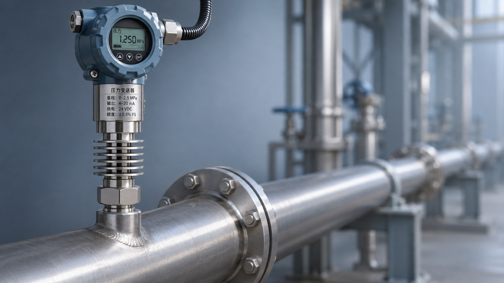
Heat-dissipating products typically use a heat-dissipating connection structure to lengthen the heat transfer path and allow the surrounding air to carry away some of the heat, reducing the temperature of the sensing element and electronic circuitry. Their compact design makes them suitable for measurement points with limited installation space and relatively stable operating conditions, provided the manufacturer confirms their suitability.
Heat dissipation is affected by ambient temperature, airflow, connection structure, and installation orientation. For locations inside enclosed insulation or near a high-temperature furnace wall, suitability cannot be determined simply from the medium temperature; the manufacturer's specified installation conditions must be checked.
These designs usually do not require additional long impulse lines, but the heat-dissipating section and connections still need regular inspection. For media subject to large temperature fluctuations, significant pressure pulsation, or corrosion, the seals, wetted materials, and pressure rating must also be checked.
Isolation cooling solutions
An isolation cooling solution uses components such as a condensing coil, impulse line, isolator, or remote diaphragm seal to shield the transmitter from direct exposure to the high-temperature medium. The specific configuration depends on the medium and process requirements. For example, pressure measurement in steam applications often uses a condensing section, while corrosive or crystallizing media may require diaphragm isolation.
Isolation cooling offers greater flexibility in adjusting the instrument position and connection method to suit site conditions. However, additional components increase the number of potential leak points, installation workload, and maintenance tasks. Diaphragms, fill fluids, and connections each have their own temperature and pressure limits, so isolation does not mean unlimited resistance to high temperatures.
The design should also account for impulse line blockage, static pressure error caused by a condensate column, and additional errors caused by temperature changes in the diaphragm seal system. The specific effects should be calculated using the installation height, line length, medium density, and manufacturer data.
3. How should temperature, response, and cost be balanced?
Check temperature against actual operating limits
The maximum medium temperature is an initial selection criterion, not the only consideration. Also confirm the continuous temperature at the pressure connection, the ambient temperature near the instrument housing, and whether heat may transfer toward the instrument after shutdown. If site temperatures approach the product limit, determine the necessary safety margin with the manufacturer.
For example, if a measurement point has a normal operating medium temperature of 120°C and an ambient temperature of 45°C, the mere fact that the temperature is “120°C” is not enough to conclude that a particular heat-dissipating instrument is suitable. You must also verify whether the medium remains at a high temperature continuously, whether the connection is covered by insulation, and what temperature the selected heat-dissipating structure permits under those installation conditions.
For steam measurement points, whether a condensing coil needs to be primed with water and how it should be installed and maintained must be determined according to the design documents and the manufacturer's requirements; do not assume that an effective volume of condensate is always present in the line. For toxic, flammable, or high-pressure media, isolation and maintenance measures should also be confirmed by qualified personnel.
Assess response time across the entire measurement chain
The rise time specified in equipment parameters usually applies to particular test conditions. It is not the total time required for a process pressure change to produce a valid signal at the control system in the field. Impulse line length and internal diameter, medium viscosity, damping settings, and the sampling interval of downstream equipment can all affect the final response.
If the measurement point is used for rapid pressure protection or capturing transient fluctuations, provide the supplier with the required response time and confirm that the connection components, transmitter, and control system meet the requirement together. Do not make a decision based solely on millisecond-level specifications for the sensing element.
In terms of cost, a heat-dissipating solution may reduce the number of accessories and the amount of installation work. An isolation cooling solution may require a higher initial investment, but under suitable operating conditions it can help protect the instrument. When comparing costs, consider procurement, installation, periodic calibration, blockage cleaning, and planned downtime together.
4. Select the product and connection method based on operating conditions
Check the range and medium first, then confirm the configuration
When selecting a range, consider normal pressure, maximum operating pressure, and possible pressure surges. Overload capacity is not a substitute for proper range selection and must not be treated as the long-term operating pressure. The rated pressures of the piping, valves, fittings, and instrument must be compatible.
Wetted materials must be compatible with the actual medium. For steam, also evaluate the condensate composition; for mixed media, consider corrosive constituents and cleaning conditions. Whether 316 or 304 stainless steel is suitable must be confirmed based on the specific medium concentration, temperature, and wetted construction.
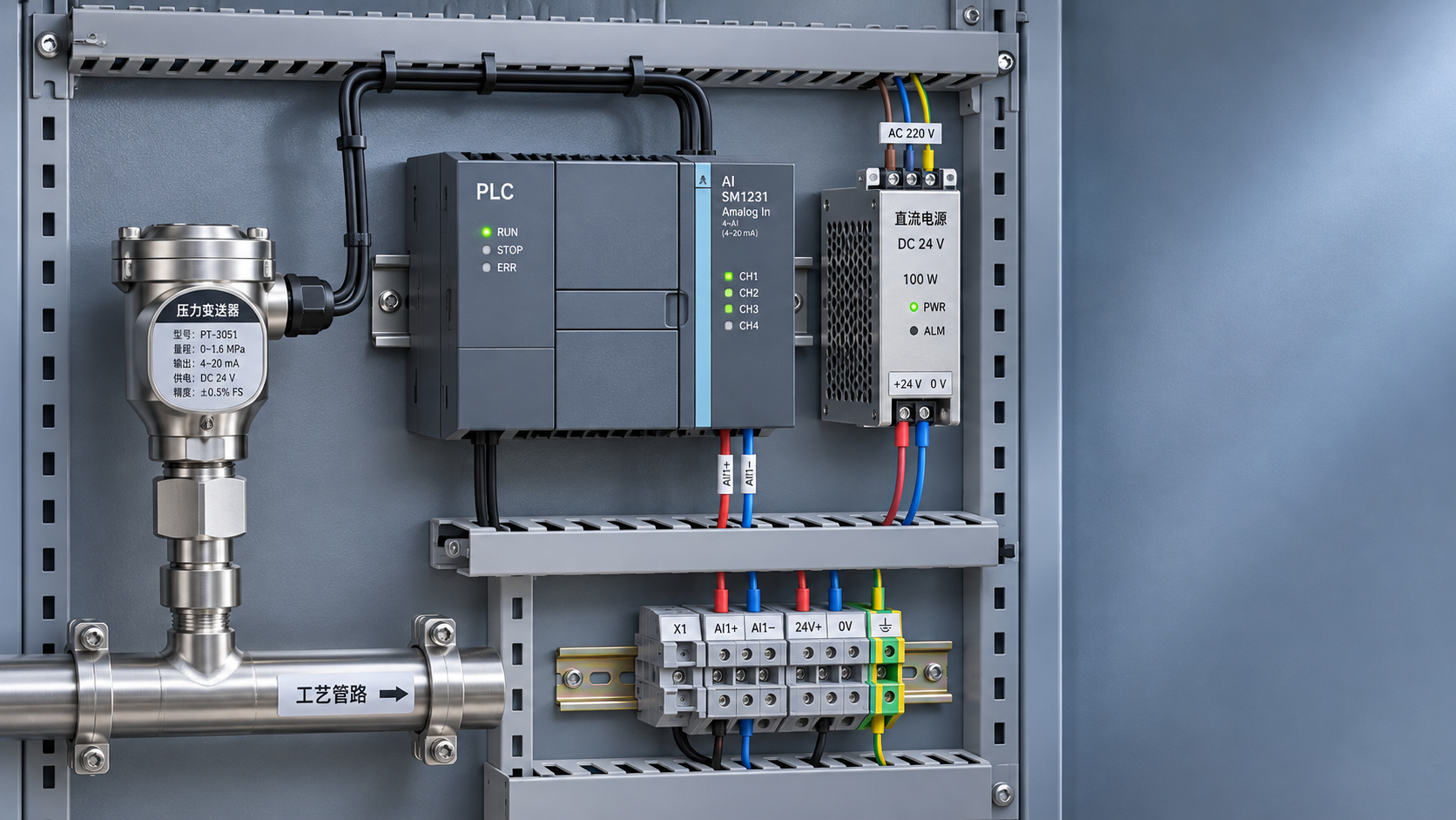
For signals and installation, check the power supply, output type, thread specification, and protection requirements. A 4–20 mA signal is commonly used for long-distance transmission, but the final choice must still match the inputs and wiring conditions of the site control system.
Example of product parameter verification
For example, the Chinese-Made High-Temperature Pressure Transmitter TXY807 Diffused Silicon 2088 Pressure Sensor is listed with sensor configurations including diffused silicon, and can be configured for gauge, absolute, and vacuum pressure measurement. The specific configuration is subject to the order confirmation documents.
The product documentation lists a medium temperature range of -30 to +85°C, an ambient temperature range of -20 to +85°C, and a temperature compensation range of 0 to 70°C. Therefore, the “high-temperature” designation in the name does not mean that the standard configuration can be directly exposed to media above 85°C. For higher temperatures, confirm with the manufacturer whether a dedicated heat-dissipating structure or isolation cooling solution is available and what its operating limits are.
The documentation also lists outputs such as 4–20 mA, two-wire, and pressure connections such as M20×1.5, G1/4, and G1/2. The actual combinations of range, accuracy, and connection must be confirmed individually during selection; do not assume that all options can be configured together.
5. Installation acceptance and ongoing maintenance
Before installation, check that the process connection, valves, fittings, and cooling accessories meet the design requirements. Leave the heat-dissipating structure the space specified by the manufacturer; arrange impulse lines and isolation components according to the process design to prevent liquid or gas accumulation, or blockage, from affecting measurement.
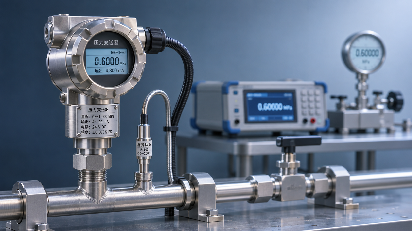
After startup, record the temperature near the instrument, pressure readings, and output status under representative conditions, including steady operation and startup or shutdown, and compare them with the permissible ranges and reference measurements. If persistent zero drift, slower response, or leakage at a connection occurs, first investigate the operating conditions and connection components, then schedule calibration or replacement.
There is no single high-temperature pressure measurement configuration suitable for every site. Xi'an Shenghongchuang Instrumentation Co., Ltd. can provide product selection and technical services based on operating conditions. To determine a suitable solution, prepare the medium name, temperature range, pressure range, connection specification, output signal, and installation photos, and review them point by point with a technical specialist.
Related Recommendations
 How to Calculate Power and Signal Compatibility When Connecting a 24 V Pressure Transmitter to a PLC
 Heat-Dissipating Pressure Transmitters vs. Isolation and Cooling Solutions: How to Choose for High-Temperature Pressure Measurement
 Compensation Principles and Temperature Drift Parameters of Temperature-Compensated Pressure Transmitters
 Selecting a High-Temperature Liquid Pressure Transmitter: How to Determine Temperature, Sealing, and Range