


News Center
—— NEWS CENTER ——
Xi'an Shenghongchuang Instrument Co., Ltd.
Contact: Mr. Zhang
Mobile: 15529283736
Email: shc-sensor@qq.com
Address: Fortune Building, Sanqiao Street, Xixian New Area, Xi'an, Shaanxi Province
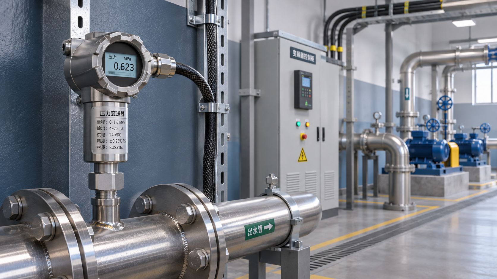
Pressure signal fluctuations near a variable frequency drive (VFD) may affect system control accuracy. When selecting a pressure transmitter with immunity to electromagnetic interference, consider not only the product’s electromagnetic compatibility, but also the power supply, wiring, and grounding conditions. Avoid attributing all fluctuations to a transmitter fault.
1. First identify the source of the signal fluctuations
A VFD uses high-speed switching to regulate motor operation. Strong electromagnetic interference may be present around its power cables and motor output cables. If the pressure transmitter’s signal cable runs parallel to power cables over a long distance or shares a cable tray with them, interference may couple into the measurement circuit.
However, changes in the displayed value are not necessarily caused by electromagnetic interference. Pump start-up and shutdown, water hammer, valve operation, and pipeline vibration can also cause actual pressure fluctuations. During troubleshooting, compare the VFD’s start-up and shutdown events and speed changes with the pressure trend to see whether the timing of the fluctuations coincides.
Also check the supply voltage, wiring terminals, acquisition module, and pressure connection. If the signal stabilizes after the VFD is shut down, this only suggests a possible link between the two. Further confirmation is required, such as temporarily changing the wiring layout, checking the power supply, or taking cross-measurements with an independent instrument.
Common symptoms and troubleshooting directions
2. Key parameters to consider when selecting a product
Immunity to interference cannot be determined from the product name alone. Before purchasing, ask the supplier to provide the applicable electromagnetic compatibility test standards, test items, levels, and criteria. Confirm that the test setup is similar to the actual power supply method, output type, and cable connections.
For applications near a VFD control cabinet, ask about test results for electrostatic discharge, electrical fast transient/burst, surge, radiated radio-frequency electromagnetic fields, and conducted disturbances. A higher test level does not mean the product will be immune to interference in every field environment; the actual interference level and installation conditions must also be considered.
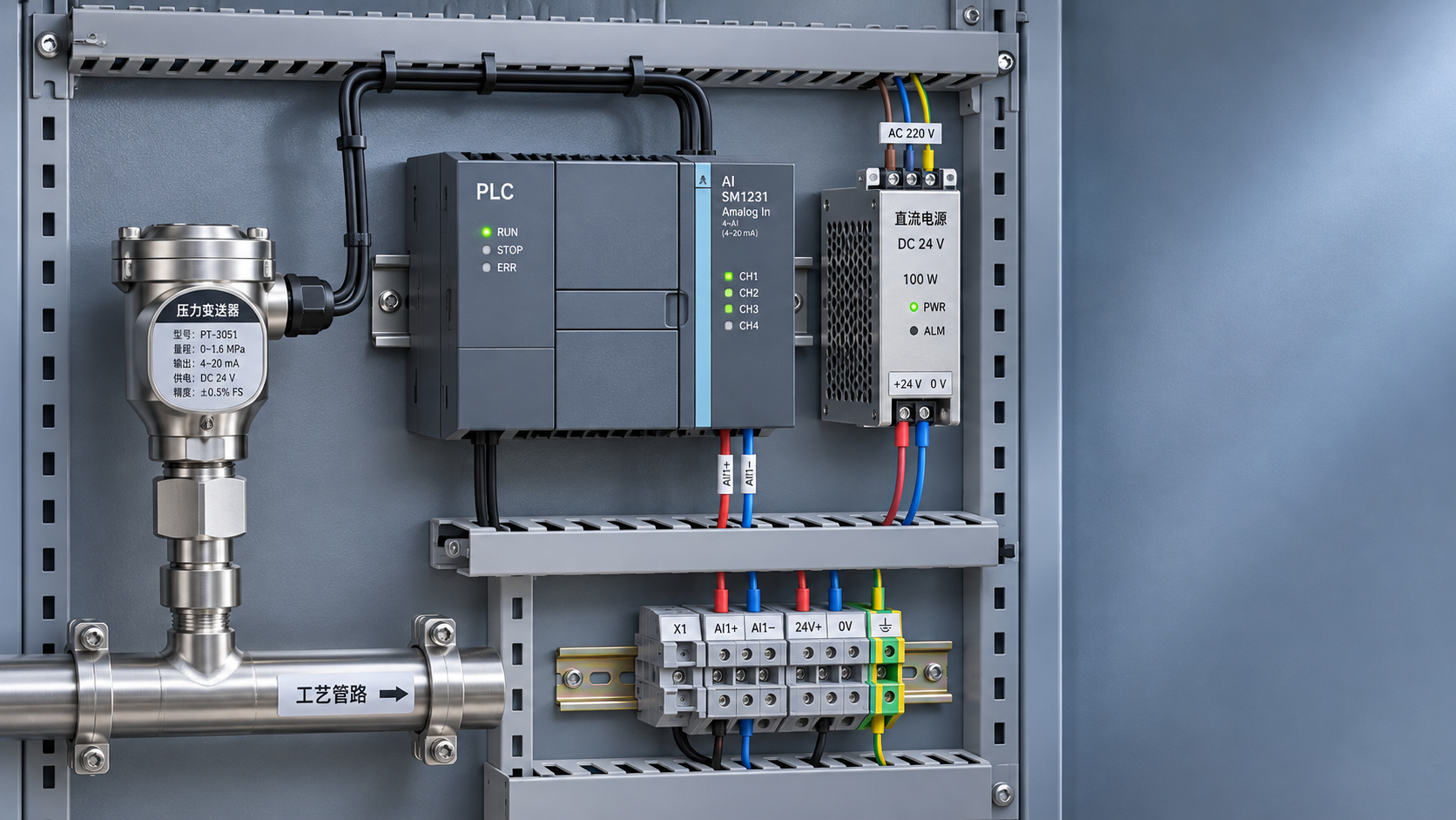
The output type also affects system design. For long-distance transmission, a 4–20 mA current signal is generally less affected by line voltage drop than a voltage signal. However, verify the loop power supply, load capacity, input type of the acquisition device, and shielding and grounding arrangements.
Match the range, accuracy, and operating conditions
The range should cover the normal operating pressure and foreseeable pressure peaks, with an appropriate margin. A range that is too small may result in damage from pressure surges, while a range that is too large reduces the effective resolution of small pressure changes. Determine the appropriate margin based on water hammer, start-up and shutdown frequency, and the equipment’s design pressure.
When selecting accuracy, check how the combined error is defined rather than looking only at the stated figure. For example, for a range of 0–1 MPa and an accuracy class of 0.5, the basic error calculated as a percentage of full scale is approximately ±0.005 MPa. Actual system error may also be affected by temperature, the power supply, and the acquisition module.
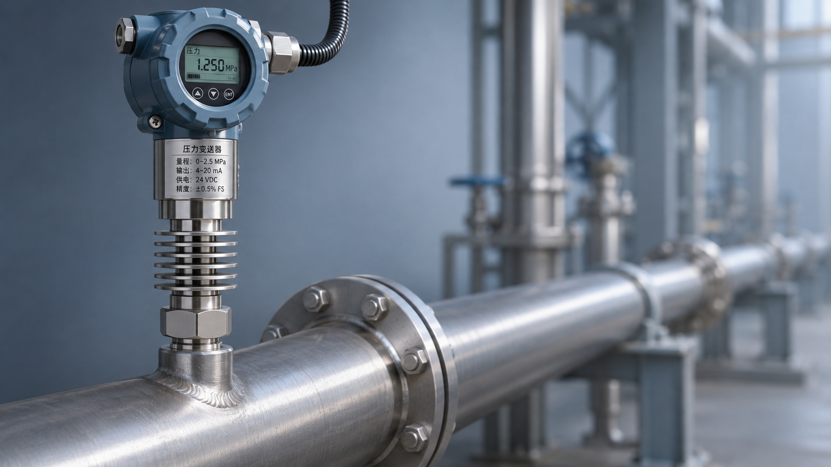
Media compatibility, operating temperature, connection thread, and degree of protection must also be considered. For steam or corrosive media, verify the wetted materials and allowable temperature. If the temperature exceeds the product’s specified limit, assess the use of a condensate siphon, isolation device, or other suitable solution.
3. Verify the product configuration against site conditions
For applications requiring a standard signal output where the medium is compatible with the wetted materials, the CHSP-202GW Domestic High-Temperature Pressure Transmitter, Diffused Silicon 2088 Pressure Sensor can be used as a selection reference. This model is available with two-wire 4–20 mA output and a range of three-wire voltage output configurations. Select the configuration according to the control system’s input interface.
According to the product documentation, the gauge pressure range covers 0–0.01 MPa to 0–250 MPa, with absolute pressure and vacuum ranges also available. Accuracy configurations include Class 1.0, Class 0.5, and Class 0.25. The range, accuracy, and output type must be specified when ordering; do not assume that every unit has the same configuration.
The product documentation lists a medium temperature range of -30 to +85°C, an ambient temperature range of -20 to +85°C, and wetted materials of 304 or 316 stainless steel. Even if “high-temperature” appears in the product name, use the actual allowable temperature for the selected configuration. For steam applications in particular, verify the temperature at the measurement point and the installation plan.
Order confirmation for high-interference environments
The product documentation lists four-core shielded cable, aviation plug, and DIN connector electrical connection options. The four-core shielded cable configuration is specified as IP65. Protection performance may vary with the connector and installation method, so confirm the complete configuration when ordering.
The available documentation does not specify an electromagnetic compatibility test level, so it cannot be used to conclude that this model meets the requirements of a particular high-interference environment. For use near a VFD, request test documentation for the relevant configuration from the supplier and confirm any necessary wiring and installation conditions.
Pressure connections include M20×1.5, G1/4, and G1/2. Verify compatibility with the equipment connection before installation. For pump stations with frequent start-ups and shutdowns, also confirm that pressure peaks are within the product’s allowable range; do not select a product based solely on the normal steady-state pressure.
4. Installation and commissioning determine actual performance
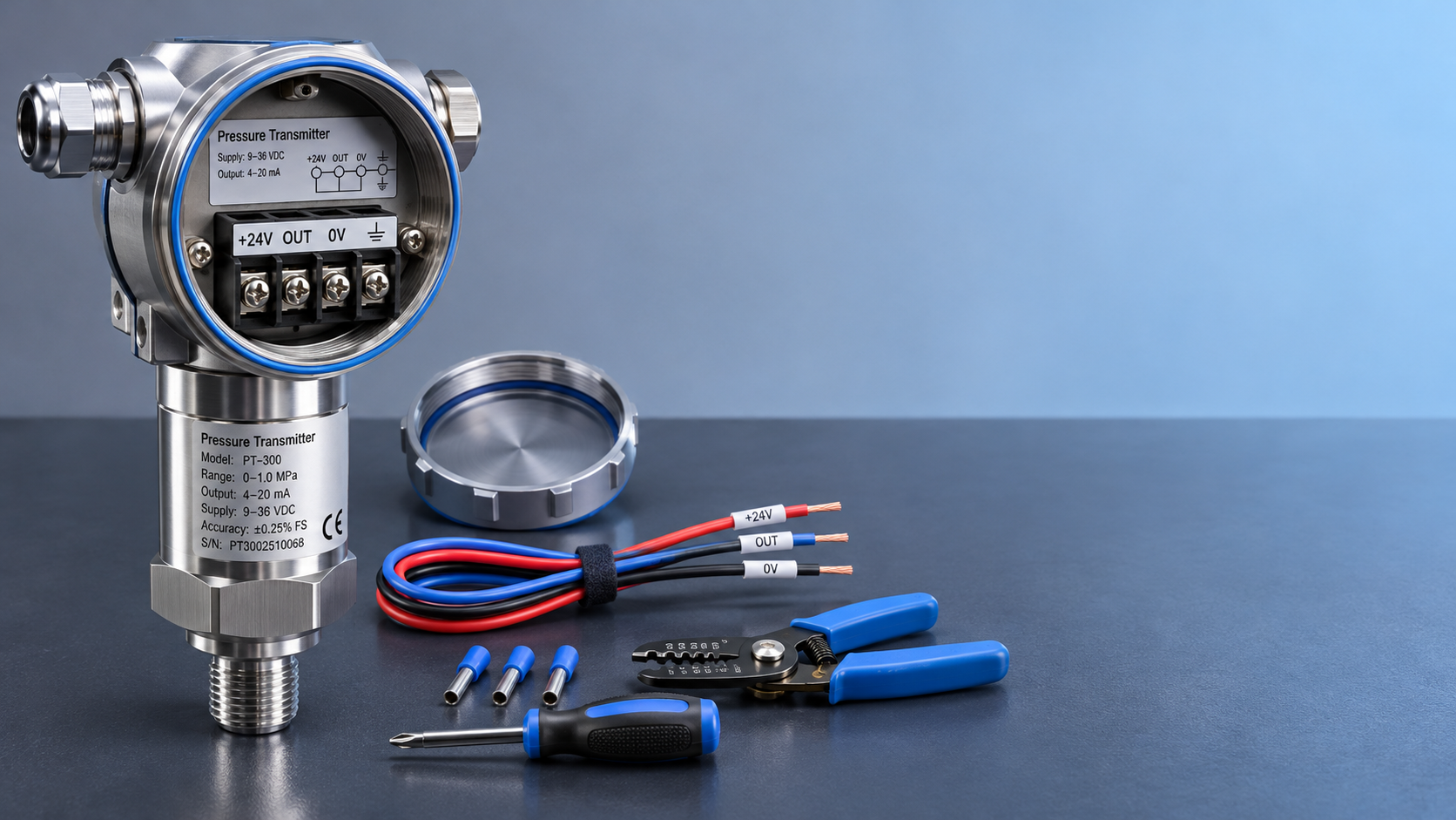
During wiring, keep the signal cable as far as possible from VFD output cables, motors, and other strong sources of interference, and avoid running it parallel to them over long distances. Where crossing is necessary, aim for an angle close to 90 degrees, as site conditions allow. Inside the control cabinet, route power cables separately from instrument signal cables.
Handle the shield of a shielded cable in accordance with the equipment manufacturer’s instructions and the system grounding standards. Single-end grounding is common, but the shield connection method should also be determined based on the interference frequency, potential differences, and equipment instructions. Consider protective grounding and shield connections separately; do not remove protective grounding arbitrarily.
During commissioning, record the pressure readings and output signals while the VFD is stopped, starting, running steadily, and changing speed. If the on-site display is stable but the control system readings are abnormal, further check the acquisition module, loop load, power supply, and signal conversion settings to avoid replacing the transmitter unnecessarily.
Prepare site information before purchasing
It is recommended to compile the medium name, normal and peak pressures, medium and ambient temperatures, required output signal, power supply conditions, mounting thread, and cable length, and to record the approximate distance between the VFD and the measurement point. This information helps the supplier determine the appropriate range, materials, and connection type.
Xi’an Shenghongchuang Instrumentation Co., Ltd. provides sales and technical services for sensors, transmitters, and related measurement and control products. Its production subsidiary is Shaanxi Qinkong Sensor Technology Co., Ltd. For operating conditions involving special media, higher temperatures, or strong electromagnetic interference, discuss the specific configuration and verification requirements during product selection.
If pressure signal fluctuations are occurring on site, provide the pressure trend, VFD start-up and shutdown records, and photos of the existing wiring when contacting technical personnel. First identify the source of the fluctuations, then verify the product test documentation and installation plan.
Related Recommendations
 Unstable Signals Near a Variable Frequency Drive? Key Selection Considerations for an EMI-Resistant Pressure Transmitter
 How to wire a 24 VDC pressure transmitter: two-wire vs. three-wire configurations
 How to Calculate Power and Signal Compatibility When Connecting a 24 V Pressure Transmitter to a PLC
 Heat-Dissipating Pressure Transmitters vs. Isolation and Cooling Solutions: How to Choose for High-Temperature Pressure Measurement