


News Center
—— NEWS CENTER ——
Xi'an Shenghongchuang Instrument Co., Ltd.
Contact: Mr. Zhang
Mobile: 15529283736
Email: shc-sensor@qq.com
Address: Fortune Building, Sanqiao Street, Xixian New Area, Xi'an, Shaanxi Province
Key Factors Affecting Long-Distance Wiring of 4-20mA Differential Pressure Sensors
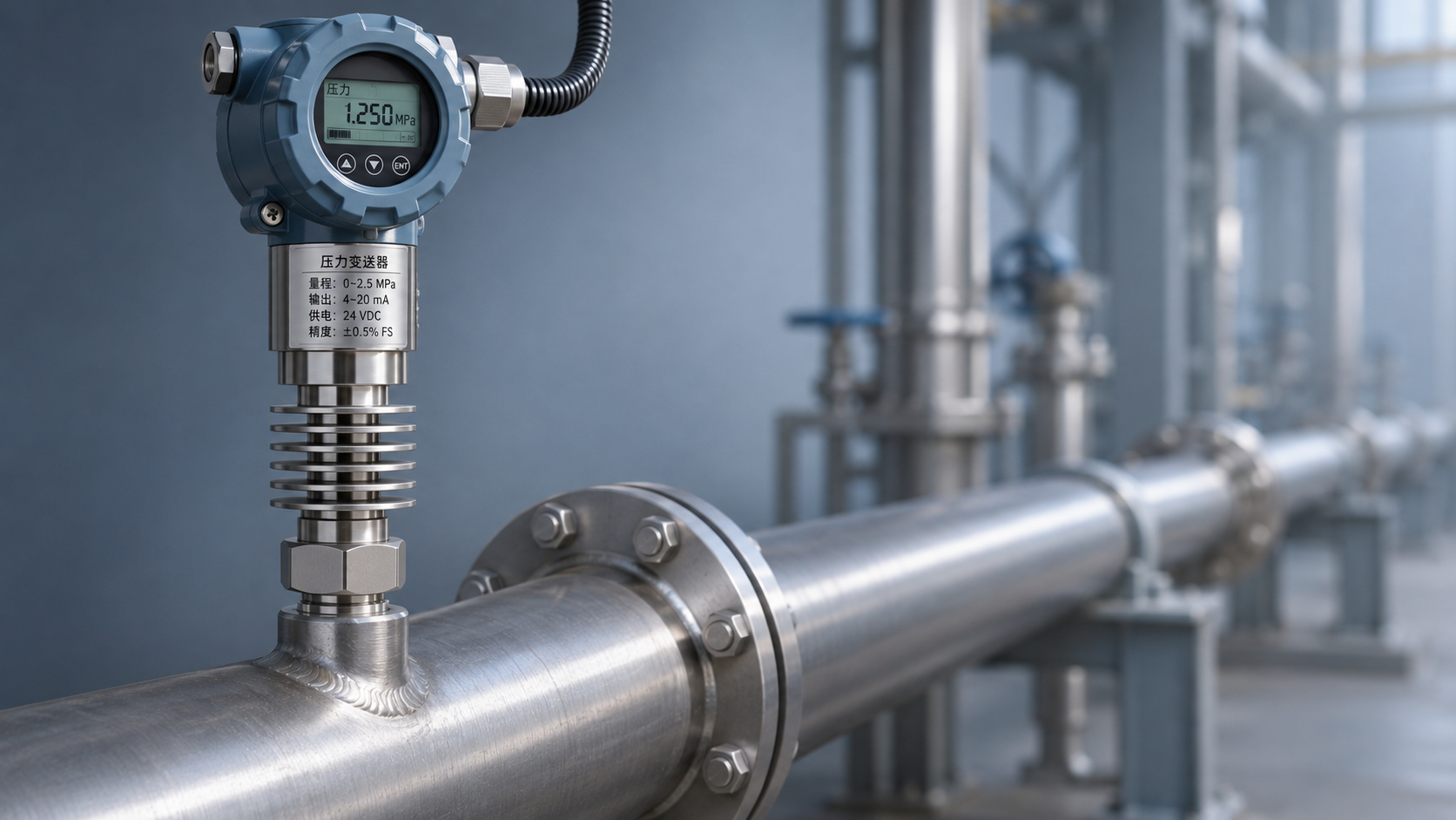
4-20mA differential pressure sensors are widely used in applications such as air pressure monitoring, filter blockage detection, liquid level measurement, pipeline flow control, and equipment differential pressure protection. Compared with voltage-type outputs, 4-20mA current signals offer long transmission distances, strong interference resistance, and the ability to detect open-circuit faults, making them suitable for long-distance measurement and control in industrial environments.
However, “long-distance transmission capability” does not mean that wiring can be handled arbitrarily. Cable impedance, supply voltage, terminal quality, shielding grounding methods, and electromagnetic interference generated by nearby equipment such as variable frequency drives, motors, and welding machines can all affect the stability of differential pressure signals. Especially at sites with distances of several hundred meters or more, supply voltage drop is often the first issue that must be calculated.
For two-wire 4-20mA differential pressure sensors, the power supply and signal share one pair of conductors. The sensor must obtain its operating voltage from the loop while converting differential pressure changes into a continuous current signal from 4mA to 20mA. Therefore, designers should simultaneously satisfy three conditions: the sensor's minimum operating voltage, the controller input load, and the cable voltage drop.
In engineering practice, it is not sufficient to consider only the transmission distance. The solution should be determined comprehensively based on the sensor power supply range, PLC or DCS analog input resistance, cable cross-sectional area, site environment, and explosion-proof requirements. For critical measurement points, it is recommended to complete loop calculations during the construction drawing stage and measure loaded current and terminal voltage after installation.
Cable Selection and Line Voltage Drop Calculation
Give Priority to Shielded Cables Suitable for Instrument Signals
For long-distance wiring of 4-20mA differential pressure sensors, copper-core twisted-pair shielded instrument cables should be used. The twisted-pair structure can reduce unbalanced induction generated by external magnetic fields in the two conductors, while the shielding layer can reduce the impact of high-frequency electromagnetic noise on the loop. Ordinary power cables or unshielded control cables should not be used as direct substitutes for instrument signal cables.
Under normal operating conditions, 0.5mm², 0.75mm², and 1.0mm² copper-core shielded twisted-pair cables are commonly used. When the distance is short and on-site interference is weak, 0.5mm² cable can generally meet the requirements. When the cable run exceeds 300m, the ambient temperature is high, or the supply voltage is low, the conductor cross-sectional area should be increased appropriately to reduce loop voltage drop.
For outdoor installation, attention should be paid to cable weather resistance, UV resistance, and waterproof performance. For cable tray installation, flame-retardant rating and mechanical protection should be considered. In corrosive environments such as chemical and metallurgical applications, corrosion-resistant sheath materials should be selected. If explosive gases are present on site, appropriate explosion-proof wiring methods and protective measures must also be selected according to the hazardous area classification.
Differential pressure sensor wiring should minimize intermediate connection points. Each additional terminal block, junction box, or temporary connector increases the risk of contact resistance, moisture-induced oxidation, and loosening failure. Where transfer connections are necessary, reliable terminals should be used, and their tightening condition should be checked during commissioning and regular inspections.
Calculate Voltage Drop and Load Capacity Based on Maximum Current
Voltage drop calculations should be based on the 20mA full-scale current rather than estimated solely from normal operating current. The line voltage drop of a two-wire loop can be calculated as “current × total loop resistance.” Note that conductor length should include the combined length of the outgoing and return wires. For example, for a 300m one-way cable run, the actual conductor length involved in the voltage drop calculation is approximately 600m.
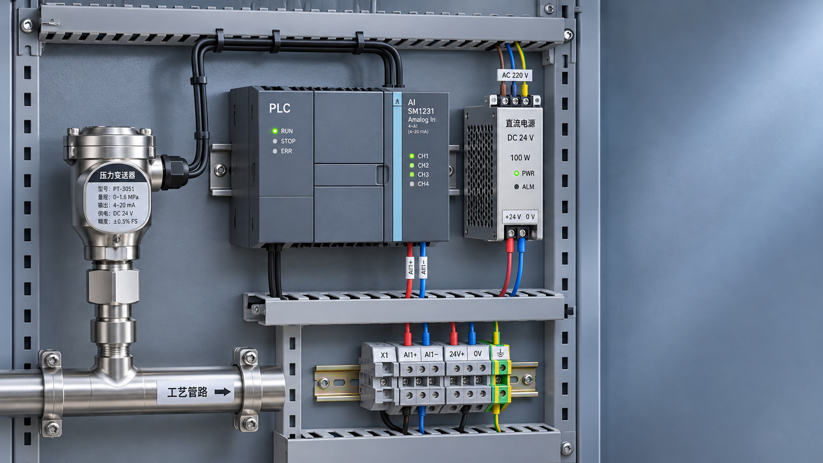
Taking a 24VDC power supply, a sensor minimum operating voltage of 10.5V, and a PLC input resistance of 250Ω as an example, the PLC input consumes approximately 5V at 20mA, leaving a theoretical margin of about 8.5V for line voltage drop. In actual engineering, this margin should not be fully used. A voltage allowance of 20% to 30% should be reserved to accommodate supply fluctuations, temperature rise, and increased contact resistance.
Some intelligent differential pressure transmitters are equipped with HART communication. In addition to the basic 4-20mA measurement loop, these products must meet the load requirements for superimposed communication signals. The loop load generally needs to reach a certain resistance value, with 250Ω being a common recommended value; however, specific requirements should be based on the product manual and control system configuration.
If calculations show insufficient power supply at the remote end, improvements can be made by increasing cable cross-sectional area, raising the supply voltage within the compliant range, shortening the transmission path, or installing an isolated power distributor on site. The power supply voltage must not be increased arbitrarily simply to “drive the loop”; it must remain below the sensor's rated maximum supply voltage.
Requirements for Interference Suppression, Shielding, and Grounding
Maintain Adequate Separation from Power Lines
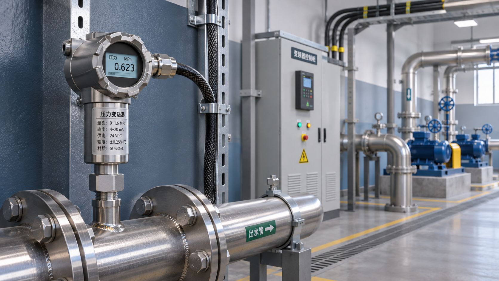
Instrument signal cables should be routed separately from 380V power cables, variable frequency drive output cables, high-power motor cables, and welding machine cables whenever possible. Where conditions permit, separate cable trays are recommended. If separate routing is not possible, metal partitions should be used for isolation, and a spacing of at least 300mm should be maintained wherever possible. For cables on the output side of variable frequency drives, the separation distance should be increased further.
When signal cables must cross power cables, they should cross vertically at an angle close to 90 degrees to avoid long parallel runs. The longer the parallel routing distance, the more pronounced the electromagnetic coupling. This may cause periodic fluctuations, instantaneous jumps, or unstable displayed values in the sensor output.
Do not route 4-20mA signal cables through the same metal flexible conduit as AC power cables, contactor control cables, or relay coil wire harnesses. Even when shielded cables are used, the shielding layer cannot completely eliminate the effects of nearby strong interference sources. Proper route planning remains the foundation of interference-resistant design.
For pump rooms, fan rooms, rolling mill areas, and large automated production lines, signal isolators or isolated safety barriers should be installed near the sensor as a priority. Isolation devices can reduce the impact of ground potential differences and common-mode interference, while also helping protect PLC and DCS analog modules as well as field instruments.
The Shielding Layer Should Generally Follow the Single-Point Grounding Principle
For the shielding layer of conventional 4-20mA differential pressure sensor signal cables, reliable single-end grounding at the control cabinet side is generally recommended, while the field sensor end should remain unconnected and be properly insulated. This directs interference current induced on the shielding layer into the grounding system while reducing the risk of ground loop currents caused by grounding at both ends.
The shielding layer should be connected to the instrument ground or the grounding terminal specified by the control system. It must not be connected arbitrarily to equipment enclosures, cable trays, or uncertain protective earth terminals. When potential differences exist between different grounding systems, incorrect grounding may instead become a new source of interference and cause signal drift.
For special high-frequency interference environments, special shielded cables, or systems for which the manufacturer clearly requires grounding at both ends, the overall electromagnetic compatibility design should be followed. Engineering personnel should not mechanically apply the single-end grounding rule, but should make judgments based on the site grounding network, equipment manuals, and system integration solution.
Protective grounding of the sensor metal enclosure and grounding of the signal shielding layer are not the same concept. The metal enclosure should be protectively grounded in accordance with equipment installation specifications. Particularly in outdoor or humid applications, applications connected to metal piping, or sites with lightning risks, grounding continuity and reliability must be ensured.
Practical Key Points for Installation Wiring and Field Commissioning
Verify the Power Supply Method and Polarity Before Wiring
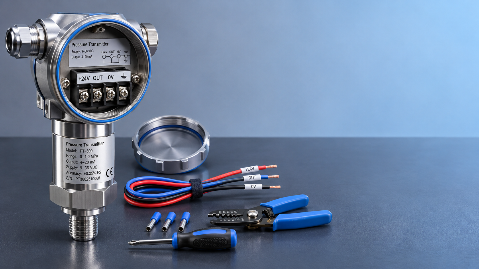
Before wiring, confirm whether the differential pressure sensor has a two-wire, three-wire, or four-wire output. Two-wire products generally complete power supply and output through the “power positive terminal” and “signal loop terminal.” Three-wire products usually require an independent common terminal, while four-wire products may have separate power supply and signal output terminals. Wiring methods for different configurations must not be mixed.
DC supply polarity must be correct. Reverse polarity may result in no output or activation of the protection circuit, and in severe cases may damage internal electronic components. Before energizing the system, it is recommended to use a multimeter to verify the 24VDC polarity at the control cabinet end and check whether the positive and negative wire markings in the field junction box are consistent with the drawings.
The wire stripping length should be appropriate to avoid short-circuit or creepage risks caused by excessively exposed copper strands. For stranded flexible wires, insulated ferrules should be crimped before insertion into terminals to improve connection reliability. Outdoor junction boxes should use waterproof cable glands, and cable entries should form a downward drip loop to prevent rainwater from entering the enclosure along the cable.
Differential pressure impulse piping is as important as electrical wiring. Reversed high-pressure and low-pressure connections will reverse the measurement direction. Blocked impulse lines, accumulated condensate, or leaking impulse tubing may appear as “abnormal signals” and can easily be misdiagnosed as cable faults. Therefore, both process connections and electrical loops should be checked when troubleshooting.
Terminal Voltage and Signal Verification Should Be Completed After Commissioning
After the system is energized, first measure the actual supply voltage at the sensor terminals, especially when the output is close to 20mA. If the terminal voltage is below the minimum operating voltage specified for the product, the device may experience output limitations during temperature changes, load variations, or supply fluctuations even if the current display appears normal.
A standard pressure source or differential pressure calibrator can be used to perform five-point tests at zero, 25%, 50%, 75%, and 100%, checking whether the outputs correspond to approximately 4mA, 8mA, 12mA, 16mA, and 20mA. For high-accuracy measurement applications, actual errors should also be recorded and compared with the sensor accuracy class and allowable system error.
If the PLC display value is unstable during commissioning, first determine whether the current loop itself is stable. Standard ammeters can be connected in series at the sensor end and control cabinet end for comparison. If the current at both ends is consistent but the host system value is abnormal, check the analog module range and program conversion. If the loop current fluctuates, focus on interference, poor contact, and power supply quality.
It is recommended to establish measurement point records documenting the differential pressure sensor model, range, supply voltage, cable model, installation distance, shielding grounding location, initial calibration data, and maintenance date. When abnormalities occur later, the line design and equipment operating condition can be quickly traced, reducing troubleshooting time.
Selection Recommendations for Long-Distance Differential Pressure Measurement Solutions
For general differential pressure measurement projects with distances of 100m to 300m inside plant buildings, using a 24VDC power supply, a two-wire 4-20mA differential pressure sensor, 0.75mm² shielded twisted-pair cable, and separate routing from power lines can generally provide stable and reliable measurement performance. For low-pressure measurements such as filter differential pressure and air duct differential pressure, low differential pressure products matched to the actual range should also be selected.
In high-interference environments such as chemical energy, metallurgy and building materials, pumping stations, wastewater treatment facilities, and large automated production lines, isolated power distribution, shield grounding, surge protection, and waterproof and corrosion-resistant measures should be incorporated into the overall design. For cable runs exceeding 500m, it is recommended to first perform a complete loop calculation and determine, based on voltage drop results, whether to use cables of 1.0mm² or larger or field isolation modules.
Xi'an Shenghongchuang Instrumentation Co., Ltd. can provide differential pressure sensors, compatible transmitters, intelligent digital display control instruments, and non-standard customized solutions according to differential pressure range, medium characteristics, installation method, transmission distance, power supply conditions, and control system interfaces. Through coordinated design of product selection and field wiring solutions, subsequent signal fluctuations, measurement deviations, and maintenance frequency can be reduced.
If you are planning a long-distance transmission project for 4-20mA differential pressure sensors, it is recommended to provide information such as transmission distance, supply voltage, PLC or DCS input parameters, on-site interference sources, and measurement medium. Professional technical personnel can then calculate cable cross-sectional area, loop load, isolation protection, and installation method to determine a measurement solution better suited to actual operating conditions.
Related Recommendations
 Unstable Signals Near a Variable Frequency Drive? Key Selection Considerations for an EMI-Resistant Pressure Transmitter
 How to wire a 24 VDC pressure transmitter: two-wire vs. three-wire configurations
 How to Calculate Power and Signal Compatibility When Connecting a 24 V Pressure Transmitter to a PLC
 Heat-Dissipating Pressure Transmitters vs. Isolation and Cooling Solutions: How to Choose for High-Temperature Pressure Measurement