News Center
—— NEWS CENTER ——
Xi'an Shenghongchuang Instrument Co., Ltd.
Contact: Mr. Zhang
Mobile: 15529283736
Email: shc-sensor@qq.com
Address: Fortune Building, Sanqiao Street, Xixian New Area, Xi'an, Shaanxi Province
Wiring Method for 1-5V Pressure Transmitter Output Signals
1-5V pressure transmitters typically use a three-wire voltage output method and are widely used in equipment control cabinets, PLC analog input modules, intelligent digital display instruments, and remote monitoring systems. Their output signal uses 1V to represent the lower range limit and 5V to represent the upper range limit, providing a relatively intuitive basis for open-circuit identification, zero-point determination, and full-scale monitoring. Proper wiring not only affects whether the displayed value is accurate, but also directly impacts the long-term operational stability of the equipment.
Taking a 0-1.0MPa range as an example, when there is no pressure or the gauge pressure is 0, the theoretical transmitter output is approximately 1.00V; when the pressure reaches 0.50MPa, the output is approximately 3.00V; and when the pressure reaches 1.00MPa, the output is close to 5.00V. The control system should complete parameter settings based on the transmitter range, input range, and power supply requirements, rather than connecting wires directly based only on terminal colors or field experience.
Xi'an Shenghongchuang Instrumentation Co., Ltd. and its manufacturing base, Shaanxi Qinkong Sensor Technology Co., Ltd., can provide pressure transmitters and supporting intelligent digital display control instruments for applications such as machinery manufacturing, chemical energy, automated production lines, and environmental monitoring. For operating conditions involving high temperature, high pressure, vibration, or strong electromagnetic interference, confirm the supply voltage, signal type, process connection, medium compatibility, and control system input specifications before installation.
I. First Confirm the Three-Wire Terminal Definition
Common 1-5V pressure transmitters generally have a positive power terminal, a negative power terminal, and a signal output terminal. Terminal markings may be “V+, GND, OUT” or “+24V, 0V, SIG.” Terminal arrangement, aviation connector pin configurations, and cable colors may vary among manufacturers; therefore, product nameplates, wiring diagrams, and manuals should take priority.
In typical wiring, the positive power terminal is connected to the positive DC24V terminal, the negative power terminal is connected to the negative DC24V terminal, and the signal output terminal is connected to the positive voltage input terminal of the PLC or instrument. The negative PLC analog input terminal or instrument signal negative terminal normally needs to establish a common reference point with the transmitter negative power terminal; otherwise, the input module cannot correctly identify the 1-5V signal.
In some field installations, the signal output terminal is mistakenly connected to a current input channel, or the signal negative terminal is left floating, which can easily result in faults such as a display value of 0, full-scale drift, or fluctuating readings. Before wiring, also confirm whether the control system supports 0-5V, 1-5V, 0-10V, or 4-20mA inputs. Different input systems must not be directly mixed.
II. Standard Power Supply and Signal Loop Connection
During installation, first disconnect the system power supply, then connect the power and signal cables. For models rated for DC24V power supply, the actual supply voltage should generally remain within the product-specified range, such as 12-30VDC or 15-30VDC. Excessively low supply voltage may prevent the output from reaching 5V, while excessive supply fluctuations may cause unstable readings or zero drift.
When connecting the transmitter output to a PLC, select a voltage-type analog channel and configure the corresponding range in the software. If the PLC input range is 0-10V, 1-5V can be mapped to the actual pressure range; if the input module supports 1-5V or 0-5V, select a mode consistent with the sensor output. Taking a 12-bit analog module as an example, 0-10V corresponds to a digital value of 0-4095, while a 1-5V signal corresponds approximately to a digital value of 410-2048.
Shielded twisted-pair cable is recommended for signal lines. When the cable length exceeds 20m, particular attention should be paid to shield handling. Normally, the shield should be reliably grounded at one end only on the control cabinet side to prevent ground loop currents caused by grounding both ends. Signal cables should be routed separately from 380V power lines, inverter output cables, and motor cables, with a parallel distance preferably maintained above 200mm.
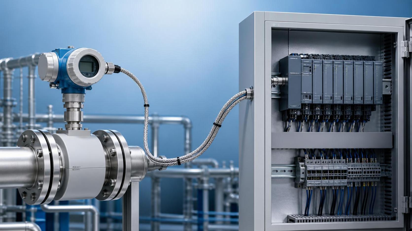
Field Wiring Logic Diagram
The basic power loop connection is: connect the DC24V positive terminal to transmitter V+, and connect the DC24V negative terminal to transmitter GND. The basic signal loop connection is: connect transmitter OUT to PLC AI+, and connect PLC AI- to the 0V common terminal. This provides the transmitter, power supply, and acquisition module with a consistent voltage reference.
If the system uses an intelligent digital display control instrument, connect OUT to the instrument voltage signal input terminal and set the input type to 1-5V according to the instrument manual. Set the lower instrument range limit to 0 and the upper limit to the actual pressure value corresponding to the transmitter, such as 1.6MPa, 2.5MPa, or 10MPa, to avoid inconsistency between the displayed unit and engineering range.
After wiring is complete, measure the voltage between OUT and GND with a multimeter under no-pressure conditions. Under normal conditions, it should be close to 1V. After slowly increasing the pressure, the voltage should increase steadily with pressure. If the pressure changes while the output remains fixed near 0V, 1V, or 5V, promptly check the power supply, terminal definition, input mode, and whether the pressure connection is blocked.
III. Conversion Between 1-5V Signals and Actual Pressure
The linear conversion formula for a 1-5V pressure transmitter is: Actual pressure = (current output voltage − 1V) ÷ 4V × span + lower range limit. For a 0-1.0MPa gauge pressure transmitter, when the measured output is 2.60V, the actual pressure is approximately (2.60 − 1) ÷ 4 × 1.0, namely 0.40MPa.
For ranges with negative pressure or non-zero lower limits, such as -0.1 to 0.9MPa, the span remains 1.0MPa, but the lower-limit value of -0.1MPa must be included in the calculation. In this case, an output of 1V corresponds to -0.1MPa, 3V corresponds to 0.4MPa, and 5V corresponds to 0.9MPa. Engineers should fully enter the upper and lower limits in PLC programs and instrument parameters.
When the system display error is significant, it is not advisable to directly modify software coefficients to conceal the issue. First verify the transmitter accuracy class, power supply stability, input module resolution, and pressure source accuracy. If the transmitter accuracy is 0.5%FS, the allowable basic error at a 1.0MPa range is approximately ±0.005MPa, and the accuracy of calibration equipment should be higher than that of the product being calibrated.
IV. Common Wiring Errors and Troubleshooting Methods
The first common issue is reversed power supply polarity. Most industrial pressure transmitters have a certain level of protection, but prolonged reverse connection may still damage internal circuits. Before wiring, use a multimeter to confirm the power output. The positive and negative terminals of a DC24V power supply must not be identified solely by wire color, especially at sites involving equipment retrofits, old cabinet maintenance, or multiple coexisting power supplies.
The second issue is an unconnected common terminal or improper grounding. If the PLC analog module and transmitter do not share a common reference terminal, the acquired value may fluctuate severely; if both ends of the shield are grounded at multiple points, interference may be introduced near frequency converters, welding equipment, or high-power motors. When fluctuations occur, first check signal ground continuity, then investigate the cable routing path.
The third issue is incorrect range, unit, or input mode settings. For example, if the actual transmitter range is 0-1.6MPa but the control system calculates it as 0-1.0MPa, the full-scale display will have a 60% deviation; if 1-5V is configured as 0-5V, the zero position will also shift significantly. After wiring is completed, perform comparison verification at a minimum of three pressure points: 0%, 50%, and 100%.
V. Pre-Commissioning Inspection and Maintenance Recommendations
Before commissioning, check whether process connections are securely sealed. In particular, for common threaded connections such as M20×1.5, G1/4, and G1/2, confirm the thread specification, sealing method, and installation torque. M20×1.5 is a metric fine thread and cannot be directly substituted with a G1/2 pipe thread. Mismatched connections may cause leakage, thread damage, or abnormal pressure measurement.
For pulsating pressure, impact pressure, or high-temperature media, configure a buffer tube, condensation bend, damper, or diaphragm seal. The standard range selection for a transmitter should preferably keep normal operating pressure within 30% to 80% of full scale. Possible transient system pressure peaks should also be considered to prevent prolonged overpressure from affecting sensor element service life.
It is recommended to establish periodic inspection records, focusing on supply voltage, zero output, full-scale response, and the difference between the field display value and the standard gauge. For critical equipment in continuous operation, perform calibration every 6 to 12 months; under complex operating conditions in chemical, energy, metallurgical, and similar industries, shorten the maintenance interval according to medium corrosiveness, vibration intensity, and frequency of use.
If confirmation is required for 1-5V pressure transmitter terminal definitions, range conversion, M20×1.5 connection compatibility, or PLC wiring solutions, provide Xi'an Shenghongchuang Instrumentation Co., Ltd. with specific application information based on the field supply voltage, control system model, medium parameters, and installation conditions, so that matching pressure sensing and measurement-control products and technical support solutions can be provided.
Related Recommendations
 What Costs Should Be Considered When Purchasing Small Flowmeters in Xi'an?
 How can Shaanxi remote-transmission flowmeters reduce signal transmission errors?
 How to troubleshoot fluctuating readings on a Xi'an gas flowmeter?
 What misconceptions should be avoided when selecting a Shaanxi liquid flowmeter?