News Center
—— NEWS CENTER ——
Xi'an Shenghongchuang Instrument Co., Ltd.
Contact: Mr. Zhang
Mobile: 15529283736
Email: shc-sensor@qq.com
Address: Fortune Building, Sanqiao Street, Xixian New Area, Xi'an, Shaanxi Province
M20×1.5 Pressure Transmitter Thread Specification Confirmation: Procurement, Installation and Measurement Essentials
When purchasing or replacing a pressure transmitter, the process connection thread is often the parameter most easily overlooked, yet most likely to cause rework. The commonly referenced “M20×1.5 pressure transmitter” does not simply mean an interface diameter of approximately 20 mm; it includes two key dimensions: nominal diameter and pitch. M20 indicates a nominal diameter of 20 mm, while 1.5 indicates an axial distance of 1.5 mm between corresponding points on the same side of adjacent threads.
For industrial measurement and control equipment such as pressure, level and differential pressure instruments, thread specifications directly affect installation depth, sealing method, pressure resistance and connection strength. Even if their outside diameters appear similar, interfaces such as M20×1.5, G1/2 and NPT1/2 cannot simply be interchanged. Forced installation may result in thread damage, medium leakage or abnormal pressure measurement.
Xi'an Shenghongchuang Instruments & Meters Co., Ltd. and its subsidiary, Shaanxi Qinkong Sensor Technology Co., Ltd., generally conduct a comprehensive confirmation of the on-site interface, medium properties, operating pressure, temperature range and electrical output method when selecting pressure transmitters and industrial sensing and measurement-control products. Verifying the thread first and then determining the measuring range and signal can significantly reduce equipment replacement risks.
I. Basic Meaning and Sealing Logic of M20×1.5 Threads
1. Nominal Diameter and Pitch Must Be Confirmed Together
M20×1.5 is a metric standard fine thread. M represents metric thread; 20 represents the nominal major diameter of the thread; and 1.5 represents the pitch. The pitch of standard M20 coarse thread is usually 2.5 mm, whereas M20×1.5 is a fine-thread specification. Therefore, confirming only a “20 mm interface” is insufficient for product selection.
Fine threads are widely used in industrial instrument connections and feature relatively more engaged threads, better connection stability and finer axial adjustment. When a pressure transmitter is installed long-term on vibrating equipment, pipeline branches or hydraulic systems, correctly matched threads help maintain connection reliability.
It should be noted that the thread itself generally does not perform the entire sealing function. Many M20×1.5 pressure transmitters use face gaskets, bonded seals, copper washers, fluororubber sealing rings or conical-face seals. When confirming an interface, thread specifications and sealing-face type should be evaluated as a whole.
2. Differences Between M20×1.5 and Common Interfaces
The outside diameter of G1/2 is approximately 20.95 mm, which is very close to an M20 interface; therefore, this is a pair of specifications frequently misidentified in the field. They differ not only in diameter, but also in pitch, thread angle and standard system. If G1/2 is mistakenly installed into an M20×1.5 female thread, it may initially appear to screw in, but continued force will damage the connector.
NPT1/2 is a tapered pipe thread that forms a seal through progressive tightening by thread taper, which differs from the connection principle of the common M20×1.5 straight thread. In chemical energy, high-pressure hydraulic or corrosive-medium applications, leakage risks caused by incorrectly mixing interfaces are higher.
When the nameplate of the original equipment indicates only “M20” or “20 thread,” it is not advisable to order directly. The pitch, male or female thread type, effective thread length, and whether there is a sealing step at the bottom of the mounting hole should be further confirmed to avoid using incomplete information in place of a standard specification.
II. How to Confirm M20×1.5 Pressure Transmitter Threads On Site
1. Measure Using Calipers and a Thread Gauge
To confirm a male thread, first use vernier calipers to measure the maximum outside diameter at the thread crest. The theoretical major diameter of an M20×1.5 male thread is close to 20 mm, while actual readings may vary slightly due to machining tolerances, coatings, wear and measurement location. During measurement, avoid thread sections with impact damage, rust or residual sealing material.
A metric thread gauge is recommended for pitch confirmation. Place the 1.5 mm pitch gauge leaf against the thread. If the tooth profile continuously fits multiple thread crests and roots, it can generally be identified as M20×1.5. Counting only one or two thread pitches is easily affected by visual errors.
If no thread gauge is available, measure the total length of 10 pitches and divide it by 10. In theory, the axial length of 10 consecutive pitches of an M20×1.5 thread is approximately 15 mm. This method is suitable for preliminary on-site verification, but a thread gauge or trial fitting with a sample is still recommended before finalizing procurement.
On-Site Confirmation Checklist
When measuring a female thread, the male thread parameters of the matching old transmitter can be checked first. If the old unit has been lost, a thread plug gauge, standard sample or a relevant fitting removed by maintenance personnel can be used for comparison. For production lines that cannot be conveniently shut down, it is recommended to photograph the front and side of the interface and the measurement readings, and retain the equipment model information.
On-site photos should clearly show the structure around the interface. In particular, hydraulic valve blocks, pressure vessel pressure taps and flange impulse-pressure devices may have installation spaces that restrict hex size, housing diameter or cable outlet direction. Identical threads do not necessarily mean that the overall transmitter structure can be installed smoothly.
For high-temperature, high-pressure, flammable, explosive or toxic medium conditions, interface estimation based on experience is not acceptable. Verification should be conducted according to equipment drawings, original procurement documents or process piping standards. When necessary, professional technical personnel should complete shutdown inspection and selection confirmation.
III. Do Not Consider Only the Thread When Replacing a Pressure Transmitter
1. Measuring Range, Accuracy and Overload Capacity Must Match Operating Conditions
After confirming the M20×1.5 interface, the pressure range should also be verified. For example, if the original equipment range is 0–1.6 MPa, a 0–10 MPa product should not be used as a replacement merely because the interface is the same. An excessively large range may reduce display resolution in the normal operating pressure range, while an insufficient range may cause over-range damage during pressure fluctuations.
In engineering practice, normal operating pressure is generally kept within 30%–80% of the measuring range, while overload requirements are assessed in combination with the system's transient surge pressure. Pressure pulses caused by startup, shutdown or valve switching are common at pump outlets, hydraulic actuators and compressed-air networks.
The accuracy class must also meet the control objective. Equipment used for general trend monitoring has different requirements for zero stability, long-term drift and repeatability than equipment used for metering assessment, closed-loop control or critical safety interlocks. Before selection, actual site control system requirements should be clarified rather than pursuing higher specifications alone.
2. Output Signal and Power Supply Method Must Be Checked Item by Item
Common industrial outputs include 4–20mA, 0–10V, 0–5V, 1–5V and RS485 communication. Two-wire 4–20mA pressure transmitters are suitable for long-distance transmission and offer good interference resistance in complex electromagnetic environments; voltage outputs depend more on power supply stability, cable distance and input impedance matching.
Taking a 1–5V output as an example, DC power supply must generally be provided according to the product wiring definition, and the signal terminal must be correctly connected to the PLC, display instrument or acquisition module. A current output must not be directly connected to a voltage input, nor should identical connector appearance be assumed to mean identical pin definitions.
Power supply voltage, load resistance, cable length, protection rating and grounding method should also be recorded. In high-interference areas involving variable-frequency drives, motors and welding machines, signal cables should be routed separately from power cables, and shielding layers should be reliably handled according to system requirements to avoid mistaking pressure signal fluctuations for process pressure changes.
IV. Common Issues in Installing M20×1.5 Pressure Transmitters
1. Incorrect Selection or Reuse of Sealing Components
Many leakage issues are not caused by incorrect thread specifications, but by mismatched sealing components. Flat-face sealing interfaces generally require correctly sized bonded seals or sealing rings; high-temperature media may require temperature-resistant materials; and oils, solvents, acidic or alkaline media require consideration of the sealing material's medium resistance.
Old copper washers, aged O-rings and compressed, deformed bonded seals should not be reused repeatedly. Even if leakage does not occur shortly after disassembly and reassembly, gradual leakage may develop after thermal cycling, vibration or pressure fluctuations, affecting pressure measurement stability and on-site safety.
Thread sealant or PTFE tape cannot replace a face seal that should originally be used. For M20×1.5 straight-thread interfaces designed to seal through face compression, excessive wrapping of sealing tape is not only of limited effectiveness, but may also allow debris to enter the pressure tapping channel or sensor cavity.
2. Improper Installation Force and Pressure Tapping Location
During installation, tighten using the designated hexagonal wrenching section specified by the product. Do not clamp the transmitter housing, display head or electrical connector directly. Tightening torque must be applied according to interface material, sealing method and manufacturer technical documentation. Excessive force may cause thread galling, damage to the isolation diaphragm or sensor zero drift.
Pressure tapping points should be kept away from pipeline elbows, pump and valve impact zones, and locations with obvious vibration whenever possible. When measuring steam, high-temperature liquids or particle-containing media, condensate bends, damping devices, isolators or impulse-pressure structures should also be installed to prevent medium temperature, pulsation and blockage from directly affecting pressure transmitter service life.
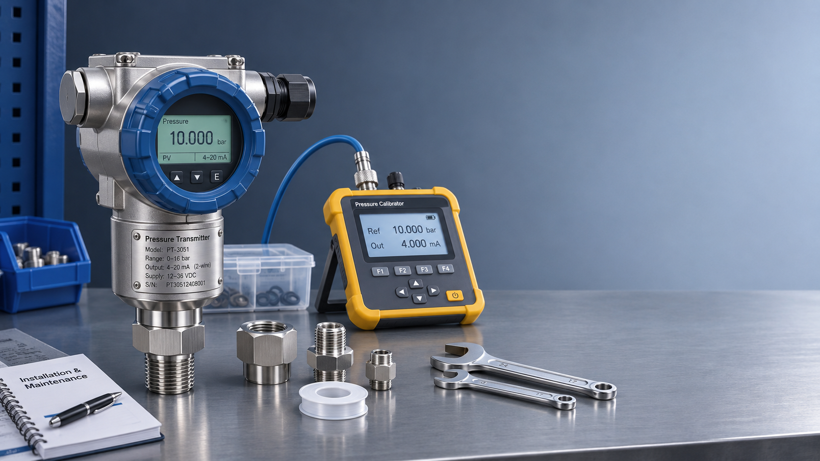
After installation, check the seal under low pressure first, then gradually increase pressure and observe whether the output is stable. For 4–20mA products, simultaneously verify whether the zero-pressure output is close to 4mA and whether full-scale output is close to 20mA. If a digital display instrument is installed on site, also check the deviation between the displayed value and the standard pressure source.
V. Procurement Confirmation Information and Technical Support Recommendations
1. Key Information to Provide Before Ordering
When purchasing an M20×1.5 pressure transmitter, it is recommended to provide the medium name, measuring range, maximum site pressure, interface specification, sealing method, output signal, supply voltage, accuracy requirement and installation environment at one time. The more complete the information, the easier it is to match a product solution suitable for conventional or complex industrial operating conditions.
If the original equipment has a nameplate, provide a nameplate photo. If the interface cannot be confirmed, provide caliper measurement photos, close-up thread photos, mounting-hole photos and an overall photo of the old unit. For non-standard equipment modification projects, installation space, cable direction, process connection material and whether local display is required should also be specified.
Xi'an Shenghongchuang Instruments & Meters Co., Ltd. can assist in verifying interface and electrical parameters for products including pressure transmitters, level transmitters, differential pressure transmitters, flow meters and intelligent digital display control instruments, and provide compatibility recommendations for applications such as machinery manufacturing, chemical energy, environmental monitoring and automated production lines.
Before replacement, first verify the M20×1.5 outside diameter, 1.5 mm pitch, sealing face and effective thread length, then submit the on-site medium, measuring range, signal and installation photos to technical personnel for confirmation. Arranging procurement and installation after parameter verification can effectively reduce mismatches, leakage and shutdown-related rework.
Related Recommendations
 RS485 Pressure Transmitter Multi-Drop Networking: How to Set the Terminating Resistor and Device Addresses?
 How Does a HART Pressure Transmitter Use an Overlay Signal for Remote Configuration?
 Cost Analysis for Purchasing Imported Pressure Transmitters: What Costs Should You Consider Beyond the Quoted Price?
 How to Select an E+H Pressure Transmitter: Key Considerations from Measuring Medium to Process Connection