News Center
—— NEWS CENTER ——
Xi'an Shenghongchuang Instrument Co., Ltd.
Contact: Mr. Zhang
Mobile: 15529283736
Email: shc-sensor@qq.com
Address: Fortune Building, Sanqiao Street, Xixian New Area, Xi'an, Shaanxi Province
Which Is Better: Strain Gauge or Piezoresistive Pressure Transmitters? Start with Measurement Principles and Operating Condition Compatibility
There is no absolute answer as to which is better between strain gauge pressure transmitters and piezoresistive pressure transmitters. The core differences lie in the pressure response mechanism of the sensing element, applicable measurement range, temperature characteristics, and long-term stability. In actual selection, initial accuracy alone should not be used as the basis for judgment. The measured medium, installation location, ambient temperature, pressure fluctuations, and control system interface should also be evaluated comprehensively.
Strain gauge pressure transmitters typically utilize the slight deformation of a metal elastic element under force, causing changes in the resistance value of bonded or integrated strain resistors, and then output a standard signal through a Wheatstone bridge and signal conditioning circuit. Their structure is relatively mature and offers good adaptability to large loads, mechanical shocks, and complex industrial sites.
Piezoresistive pressure transmitters commonly use semiconductor cores such as diffused silicon and monocrystalline silicon, which produce a pronounced piezoresistive effect when subjected to pressure. Due to the high sensitivity of semiconductor materials, piezoresistive products can achieve high-resolution measurement at lower ranges. Common outputs include 4-20mA, 0-10V, 1-5V, and RS485 communication signals.
Key Differences Between the Two Types
In terms of sensitivity, piezoresistive cores provide stronger output signals and are suitable for low-pressure, micro-pressure, and applications requiring fine resolution of pressure changes, such as water supply networks, HVAC systems, gas pressure monitoring, and precision equipment applications. For low-range applications such as 0-10kPa and 0-100kPa, piezoresistive solutions are more common.
In terms of structural load-bearing capability, strain gauge products often operate based on metal diaphragms, elastic elements, or mechanical force-bearing structures, offering greater resistance to medium and high pressures, frequent pulsation, and mechanical vibration. In hydraulic equipment, construction machinery, metallurgical equipment, and heavy-duty automation systems, overload capacity and fatigue life should be carefully verified.
In terms of temperature effects, both types may experience zero drift and sensitivity drift, but piezoresistive semiconductor cores are generally more temperature-sensitive and require digital compensation, temperature calibration, and appropriate installation to reduce errors. For operating conditions with medium temperatures above 85℃, heat sinks, capillary tubes, or remote diaphragm seal structures should also be considered.
Basic Performance Comparison
Selecting a More Suitable Pressure Transmitter Based on Range, Medium, and Temperature
A reasonable margin should be reserved when selecting the measurement range. For systems with relatively stable pressure, normal operating pressure should preferably be between 30% and 80% of full scale. For pulsating conditions such as pump start-stop operations, water hammer, and rapid valve switching, greater overload margin should be reserved to prevent zero offset or sensing element fatigue caused by long-term operation close to full scale.
The measured medium directly determines the wetted material and sealing method. For ordinary air, water, and hydraulic oil, 316L stainless steel wetted structures may be selected. For acids, alkalis, salt spray, particle-containing slurries, or high-viscosity media, the diaphragm material, O-ring material, and whether a diaphragm seal is required should be confirmed. Media incompatibility can cause corrosion, clogging, leakage, and even measurement failure.
Temperature conditions should not be assessed based solely on ambient temperature. When installed near equipment housings, steam pipelines, or hot oil piping, the actual temperature borne by the sensor may be significantly higher than the workshop temperature. The medium temperature range of standard products is commonly -20℃ to 85℃. High-temperature models can accommodate operating conditions of 150℃, 200℃, or even higher temperatures through structural optimization.
Key Considerations for Complex Sites
If strong vibration is present on site, priority should be given to the transmitter's vibration-resistant design, the rigidity of the mounting bracket, and the cable fastening method. Vibration affects more than displayed values; it can also loosen terminals, stress solder joints, or fatigue connection threads. Therefore, both mechanical and electrical installation must be properly standardized.
If the pressure source has transient impacts, such as at the outlet of a plunger pump, hydraulic station, or air compressor, it is recommended to install a buffer tube, damper, or pressure gauge valve. Protective accessories do not alter the sensor range, but they can reduce the frequency at which pressure spikes act directly on the sensing core, which is meaningful for improving long-term stability.
For media that are prone to crystallization, solidification, or contain impurities, pressure taps should not be located in deposition areas. If necessary, select flush diaphragm, flush-mounted diaphragm, or pressure transmitters with flushing structures to reduce dead zones on the diaphragm surface and minimize problems such as abnormal zero points and delayed response caused by clogging.
Reference for Typical Operating Condition Selection
Accuracy, Stability, and Output Signals Should Not Be Compared in Isolation
An accuracy class indicates the allowable error range, rather than the actual error under all operating conditions. For example, for a Class 0.5 product with a 1MPa full scale, the basic allowable error is approximately ±0.005MPa; for a 0.1MPa range, Class 0.5 corresponds to an error of approximately ±0.0005MPa. Therefore, if the selected range is too large, the actual control resolution will decrease even when the nominal accuracy is the same.
Long-term stability is more suitable for evaluating product reliability after continuous operation. In industrial environments, temperature cycling, pressure pulsation, power fluctuations, and electromagnetic interference can all affect measurement results. When selecting a product, attention should be paid to annual stability, zero temperature drift, span temperature drift, and repeatability, rather than comparing only single test data from factory calibration.
In most industrial control applications, 4-20mA remains a high-priority output method. Current signals support longer transmission distances and offer better interference resistance, while 4mA can be used to identify open-circuit or fault conditions. Voltage outputs such as 0-10V and 1-5V are suitable for short-distance applications, inside control cabinets, or equipment integration, but shielding, grounding, and common power grounding should be properly implemented.
Wiring and Control System Compatibility
Two-wire 4-20mA pressure transmitters are typically powered by 24VDC. The positive terminal of the power supply is connected to the positive terminal of the transmitter, and the signal loop returns to the negative power terminal through the PLC analog input module. Before wiring, it is necessary to confirm whether the input module is an active or passive input to avoid duplicate power supply or failure to establish the loop.
A 1-5V pressure transmitter often corresponds to the voltage range obtained by converting 4-20mA through a 250Ω sampling resistor. If the control system directly collects a 1-5V signal, the input impedance, common terminal connection method, and power polarity should be checked. Where cable distances are long, voltage drop and external interference may cause display deviations.
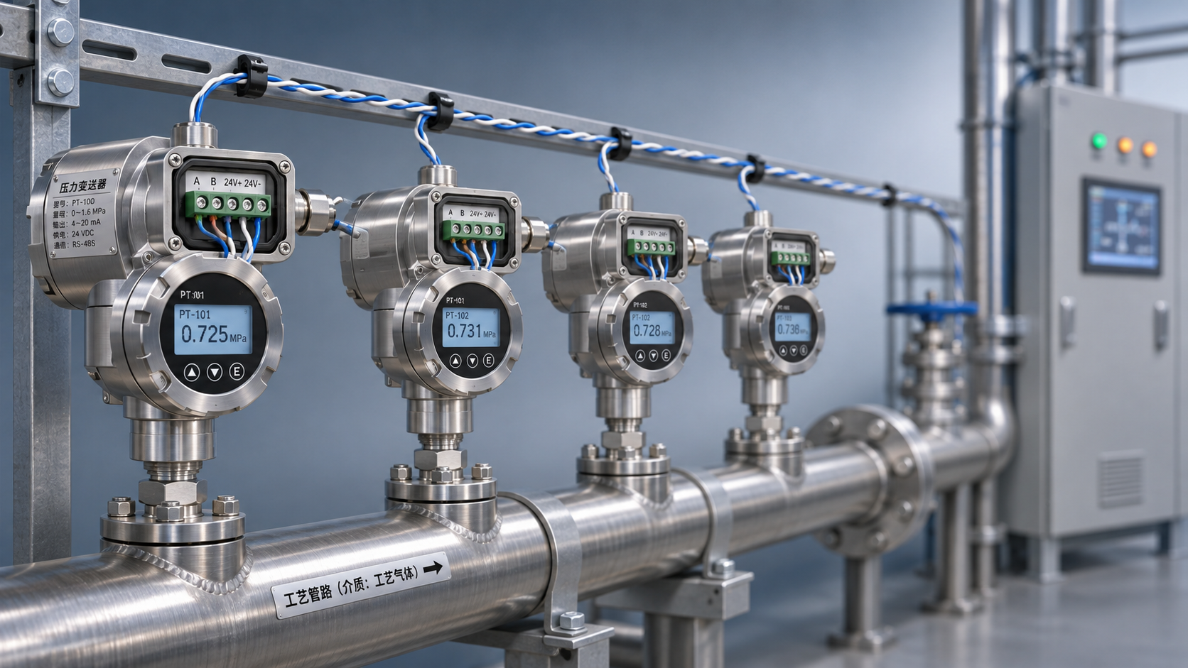
For RS485 communication pressure transmitters, the communication protocol, device address, baud rate, and termination resistor should also be confirmed. When multiple devices are connected in parallel, bus topology wiring is recommended to avoid communication reflections caused by star wiring. The shielding layer should generally be grounded at one end to reduce ground loop interference.
Specifications to Confirm Before Purchasing to Avoid Installation Mismatches
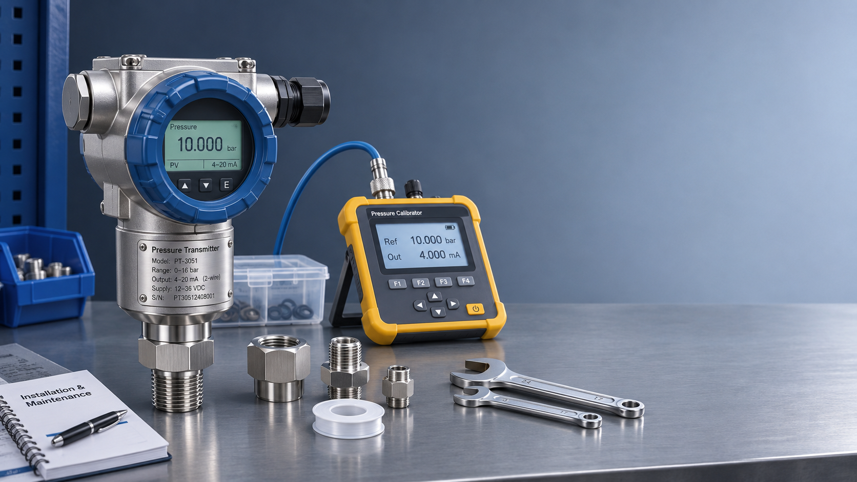
The threaded connection must match the equipment pressure tap. Common specifications include M20×1.5, G1/4, G1/2, and NPT1/4. Among these, M20×1.5 refers to a metric fine thread with a nominal diameter of 20mm and a pitch of 1.5mm; it cannot be mixed with G1/2 or NPT threads based solely on appearance. Mismatched connections can result in installation failure or unreliable sealing.
In addition to threads, the pressure range unit, pressure type, and installation orientation should also be specified. Gauge pressure is suitable for conventional pressure measurement under atmospheric conditions; absolute pressure is suitable for vacuum systems or systems requiring elimination of atmospheric pressure effects; sealed gauge pressure is suitable for specific reference pressure conditions. The selection logic for vacuum pressure, compound pressure, and differential pressure products also differs from that for standard gauge pressure transmitters.
Production and quality control capabilities affect batch consistency. Xi'an Shenghongchuang Instruments Co., Ltd. and its Shaanxi Qinkong Sensor Technology Co., Ltd. production base can provide product support and non-standard customization services for industrial measurement and control needs involving pressure, level, weighing, displacement, force, torque, temperature and humidity, and flow, while controlling product quality through raw material screening, precision machining, program commissioning, accuracy calibration, finished product inspection, and factory acceptance.
Information Recommended When Submitting Selection Requirements
It is recommended to provide at least the medium name, normal pressure, maximum pressure, pressure fluctuation conditions, medium temperature, ambient temperature, installation connection, and output signal. The more complete the information, the more effectively issues such as “the range is usable but service life is insufficient” or “the connection can be installed but the seal is incompatible” can be avoided.
For automation retrofit projects, the input type of the PLC or instrument, supply voltage, cable length, and whether variable-frequency drives and high-power equipment are present should also be specified. If electromagnetic interference on site is strong, 4-20mA output, shielded cables, and standardized grounding solutions should be prioritized, with signal isolation implemented at the control end.
Strain gauge pressure transmitters are more suitable for medium- and high-pressure operating conditions where mechanical strength, overload capacity, and fatigue resistance are key considerations; piezoresistive pressure transmitters offer advantages in low-pressure sensitivity, general industrial integration, and high-resolution measurement. Once application conditions are determined, complete parameters can be provided to professional technical personnel to verify the core type, range, connection, material, output, and accuracy class, enabling a pressure measurement solution better suited to the site.
Related Recommendations
 RS485 Pressure Transmitter Multi-Drop Networking: How to Set the Terminating Resistor and Device Addresses?
 How Does a HART Pressure Transmitter Use an Overlay Signal for Remote Configuration?
 Cost Analysis for Purchasing Imported Pressure Transmitters: What Costs Should You Consider Beyond the Quoted Price?
 How to Select an E+H Pressure Transmitter: Key Considerations from Measuring Medium to Process Connection