


News Center
—— NEWS CENTER ——
Xi'an Shenghongchuang Instrument Co., Ltd.
Contact: Mr. Zhang
Mobile: 15529283736
Email: shc-sensor@qq.com
Address: Fortune Building, Sanqiao Street, Xixian New Area, Xi'an, Shaanxi Province
Abnormal 0-5V differential pressure sensor output: the power supply can indeed be a significant contributing factor
A 0-5V differential pressure sensor typically converts the pressure difference between two measured points into a continuous voltage signal. A common relationship is 0V for zero differential pressure and 5V for the rated full-scale differential pressure. When issues such as unstable readings, zero drift, consistently high or low output, signal fluctuations, or failure to reach full scale occur on site, the sensor should not simply be considered damaged; power supply quality often needs to be checked first.
Most industrial 0-5V differential pressure sensors use a 12-24VDC power supply. Some products allow an extended supply range of 9-30VDC or 10-30VDC. When the supply voltage falls below the product's specified lower limit, the internal amplification, voltage reference, and signal-conditioning circuits cannot operate properly. The output voltage may be compressed, meaning that the differential pressure increases while the output changes only within a narrow range.
Conversely, if the supply voltage exceeds the permitted upper limit, it may cause internal voltage regulators to overheat and increase measurement errors, or in severe cases, damage the sensing element and circuitry. This is particularly relevant in systems where a 24V switching power supply has a high no-load voltage and experiences significant transient surges after high-power loads are connected. A normal average value measured with a multimeter does not mean the sensor's instantaneous supply voltage is stable.
Therefore, abnormal 0-5V output is not simply a matter of whether it is related to the power supply. It is jointly related to supply voltage, ripple amplitude, transient fluctuations, common-ground configuration, and line voltage drop. During maintenance or commissioning, measure the supply voltage directly at the sensor terminals rather than only at the control cabinet power output terminals.
First distinguish between power supply issues and sensor-related issues
Typical symptoms of insufficient supply voltage
When the power supply is rated at 24VDC but the actual voltage at the sensor terminals is only 10V, 11V, or lower, focus on checking cable length, conductor cross-sectional area, terminal oxidation, and power supply load capacity. In long-distance wiring, voltage drop caused by undersized conductors may result in normal power inside the cabinet while the field sensor is in an undervoltage condition.
For example, if a differential pressure sensor requires a 10-30VDC supply, its terminal voltage may be 24.1V at no load but drop to 9.6V after a fan, solenoid valve, or variable-frequency device starts. The output may then change from a stable 2.50V to below 2.20V. Such faults are often intermittent and can easily be mistaken for sensor zero drift.
Abnormalities caused by undervoltage do not necessarily result in an immediate zero output. Some products may still output apparently reasonable signals such as 0.3V, 1.2V, or 3.8V, but their linearity has already deteriorated. For a product with a 0-1kPa range and 0-5V output, 1V theoretically corresponds to approximately 0.2kPa. If the power supply is unstable, the differential pressure value calculated by the PLC will show systematic deviation.
When checking, it is recommended to use a high-accuracy digital multimeter to read the voltage at the sensor's positive and negative supply terminals before equipment startup, at the instant of startup, and after stable operation. If dynamic fluctuations exceed the range specified in the product manual, resolve the power supply issue first and then recheck the zero point and span.
Effects of ripple, pulsation, and transient interference
A compliant average DC supply voltage does not mean the output is completely stable. Low-quality or aging switching power supplies may have substantial AC ripple. If ripple is superimposed on the sensor supply terminals, it can affect the analog output through the internal power circuit, resulting in periodic fluctuations on the PLC display.
For precision differential pressure measurement applications, special attention should be paid to the peak-to-peak power supply ripple. Under normal circumstances, sensor supply ripple should be controlled within 100mVpp whenever possible. For low-range, low differential pressure, or high-resolution acquisition applications, lower ripple is more conducive to obtaining a stable 0-5V signal.
Variable-frequency drive startup and shutdown, high-power contactor engagement, motor reversing, and solenoid valve operation can all generate short-term interference. If the sensor shares the same 24V power supply with these loads, brief voltage drops or spikes may cause the output signal to jump suddenly by 0.1V to 0.5V, which may already exceed the allowable process range when converted into actual differential pressure.
An oscilloscope can be used to observe waveforms at the power supply and signal terminals, and voltage changes at the moment an abnormality occurs should be recorded in particular. If an oscilloscope is temporarily unavailable, connect the sensor to an independent, well-regulated DC24V power supply for comparison testing. If the signal becomes stable after independent power is applied, the original power supply or on-site interference can generally be confirmed as the issue.
On-site troubleshooting methods for abnormal 0-5V signals
Measure in sequence from the terminals to the control system
Troubleshooting should begin at the sensor terminals. First confirm that the wiring definitions for the positive supply, negative supply, signal output, and signal ground match the product label. A three-wire 0-5V sensor generally includes positive supply, common negative, and positive signal terminals, with the common negative typically serving as both the supply reference ground and the signal reference ground.
Then directly measure the voltage from “signal positive to signal ground” at the sensor output and compare it with the measured value at the PLC analog input terminal. If the sensor terminal remains stable at 2.50V while the PLC terminal fluctuates between 2.20V and 2.80V, troubleshooting should focus on the signal cable, shield grounding, terminal contact, or PLC input module.
If the sensor output itself is abnormal, further confirm whether the actual differential pressure is stable. Relevant fans, valves, or process branches can be shut down, and the output can be observed as pressures on both sides approach equilibrium to see whether it is close to zero. Note that zero differential pressure does not necessarily equal exactly 0.000V; the specific allowable deviation should be based on the product accuracy class and factory calibration specifications.
For differential pressure sensors with small measurement ranges, installation orientation, water accumulation in pressure taps, blocked impulse lines, and reversed positive and negative pressure chambers can all cause abnormal output. Power supply inspection is essential, but it must be assessed together with pressure piping and actual operating conditions to avoid replacing the sensor directly based on a single reading.
Wiring and grounding must not be overlooked
A 0-5V signal is a voltage-type analog signal, and its interference immunity is noticeably affected by wiring. Shielded twisted-pair cable is recommended for the signal cable, and it should be kept a reasonable distance from variable-frequency drive output cables and motor power cables. When routed in parallel over long distances, induced interference may be directly superimposed on the 0-5V signal.
Single-end grounding is generally recommended for the shield layer, while the specific grounding location should follow the control system design. If both ends of the shield are grounded and there is a potential difference between the grounding points, a ground loop may form and instead introduce power-frequency interference, causing irregular output voltage fluctuations.
The power supply negative terminal and the PLC analog common terminal must have a correct and reliable reference relationship. A floating common terminal, excessive contact resistance, or incorrect connection to protective earth may leave the signal without a reference baseline, resulting in 0V, a full-scale 5V deviation, or random fluctuations.
On-site terminals should be regularly checked for tightness. After terminals become loose, oxidized, or damp, their resistance may vary with vibration and temperature, causing the signal to jump from 1.80V to 2.10V. For environments with dust, humidity, or corrosive gases, junction boxes with appropriate protection ratings and cable sealing measures should be selected.
Establish practical power supply and verification standards
Recommended inspection parameters and handling principles
To reduce recurring faults, differential pressure sensor power supply checks can be incorporated into the equipment inspection checklist. For systems rated at 24VDC, it is recommended to confirm at the sensor terminals that the actual voltage is within the product's allowable range and to record changes before and after loads are connected. If multiple sensors on site exhibit abnormalities simultaneously, the common power supply capacity and distribution circuit should be checked first.
A certain capacity margin should be reserved for sensor power supplies, and long-term operation close to rated full load is not recommended. For circuits simultaneously connected to PLCs, display instruments, relays, solenoid valves, and multiple transmitters, the maximum startup current must be calculated rather than only the normal steady-state current.
After power supply rectification is completed, verify the output using a standard pressure source or reliable operating points. Taking a 0-5V output and a 0-10kPa range as an example, 0kPa, 5kPa, and 10kPa should theoretically correspond approximately to 0V, 2.5V, and 5V, respectively. If the output at each point still deviates significantly after the power supply is stabilized, professional calibration or servicing should be arranged.
Blindly turning the zero or span adjustment components before confirming the status of the power supply, wiring, and pressure piping is not recommended. Incorrect adjustment may mask the actual fault and disrupt the original calibration relationship, increasing the difficulty of subsequent metrological restoration.
For ventilation systems, filtration systems, clean rooms, air duct monitoring, and industrial automation equipment requiring long-term stable differential pressure data acquisition, it is recommended to select differential pressure sensors with clearly specified power supply tolerance, reliable interference immunity, and complete factory calibration, and retain technical documentation such as the range, output mode, power requirements, and wiring diagram.
Xi'an Shenghongchuang Instrumentation Co., Ltd. can provide 0-5V differential pressure sensors and supporting measurement and control solutions based on the actual medium, differential pressure range, power supply conditions, installation environment, and control system interface. When output abnormalities occur, on-site measured power supply values, output voltage, wiring method, and operating condition information can be compiled for technical personnel to provide targeted assessment and selection support.
Related Recommendations
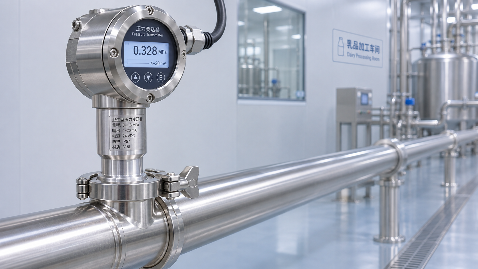
 What hygienic design and cleaning requirements should be checked when purchasing a milk pressure transmitter?
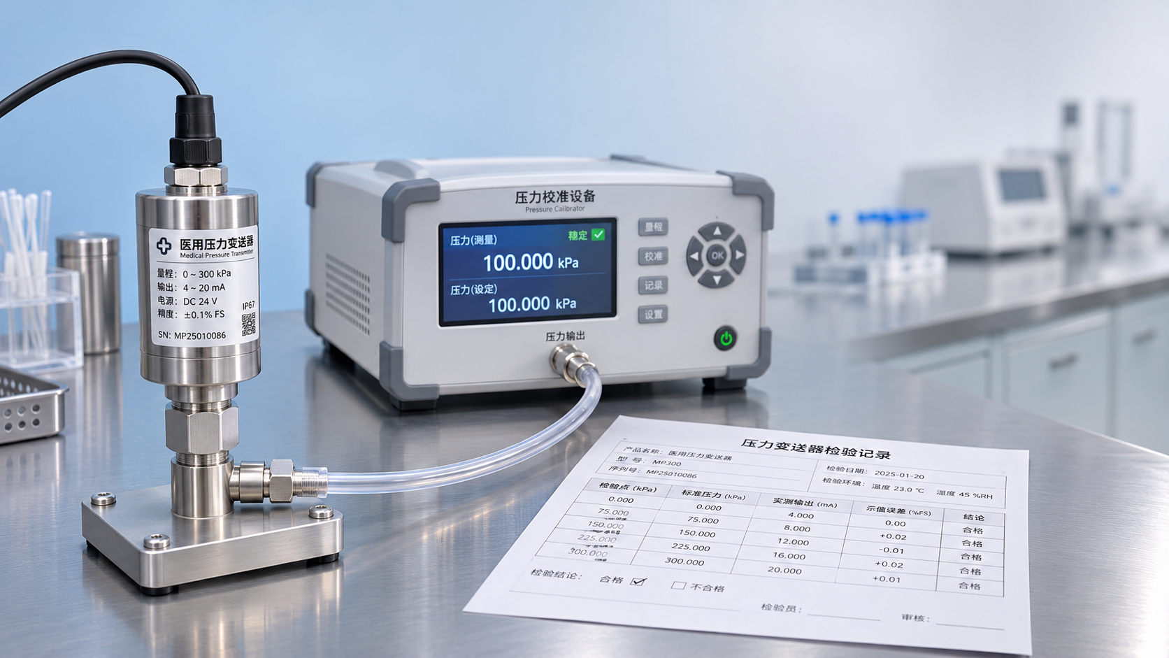
 What compliance requirements should be checked when using a medical pressure transmitter in medical equipment?
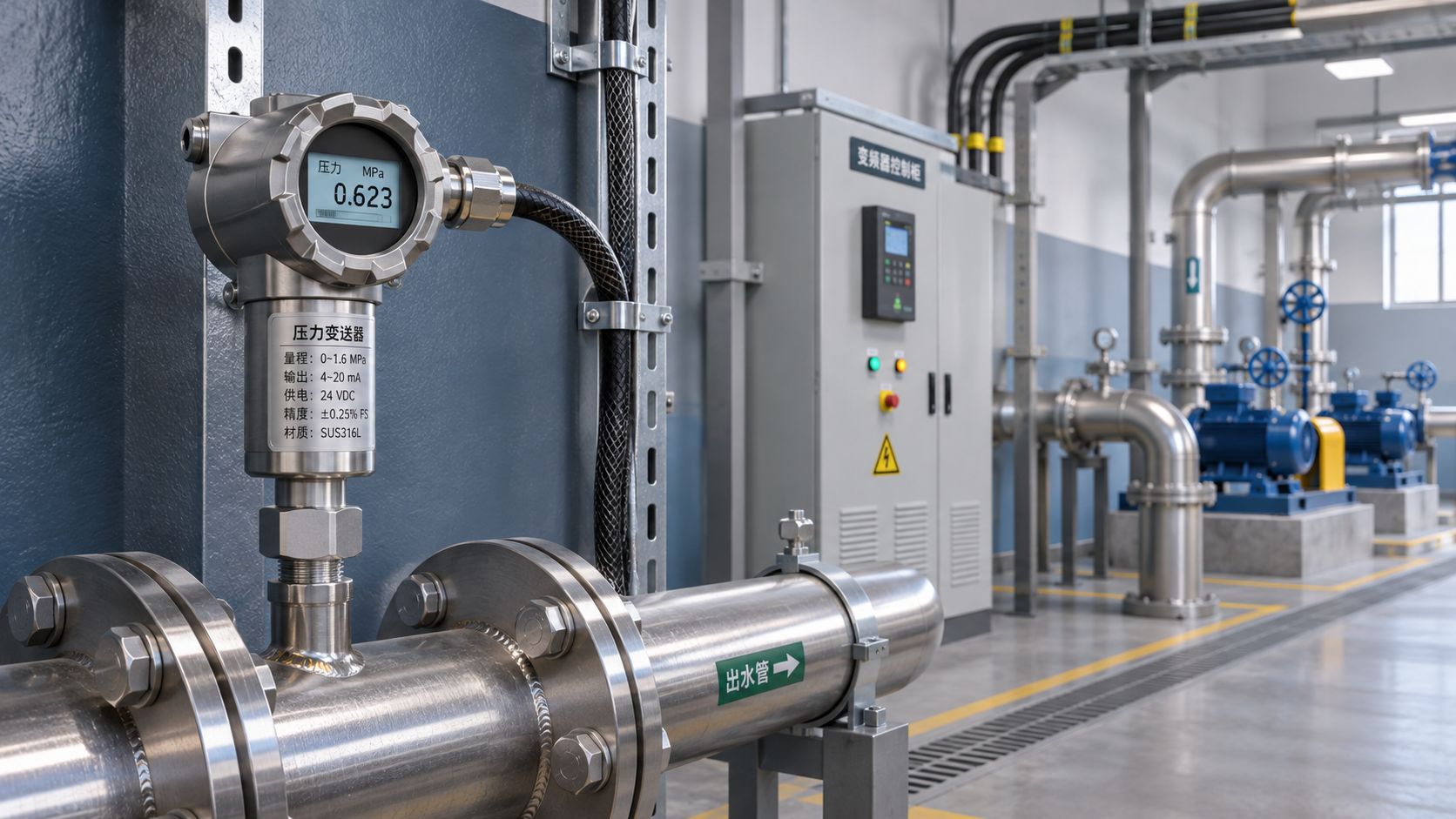
 Unstable Signals Near a Variable Frequency Drive? Key Selection Considerations for an EMI-Resistant Pressure Transmitter
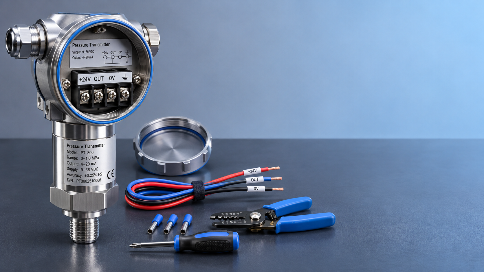
 How to wire a 24 VDC pressure transmitter: two-wire vs. three-wire configurations