


News Center
—— NEWS CENTER ——
Xi'an Shenghongchuang Instrument Co., Ltd.
Contact: Mr. Zhang
Mobile: 15529283736
Email: shc-sensor@qq.com
Address: Fortune Building, Sanqiao Street, Xixian New Area, Xi'an, Shaanxi Province
Where Do Signal Transmission Errors in Shaanxi Remote Flow Meters Come From?
In chemical energy, water supply metering, automated production lines, and environmental monitoring applications, Shaanxi remote flow meters not only collect instantaneous flow data but also need to transmit data reliably to PLCs, DCSs, intelligent digital display instruments, or remote monitoring platforms. When the on-site display is normal but the host computer data fluctuates, is lost, or shows increasing deviation, the issue often lies in the signal transmission link rather than in the flow sensing element itself.
Common sources of error include unstable power supply, improper cable selection, incorrect grounding methods, electromagnetic interference, mismatched communication parameters, and installation environments beyond the instrument's applicable range. For 4-20mA analog signals, additional contact resistance, voltage drop, or common-mode interference in the loop may cause the control system reading to deviate from the actual measured value.
Reducing errors should not rely solely on backend software correction. Instead, flow meter selection, installation, wiring, commissioning, calibration, and maintenance should be controlled in parallel. Xi'an Shenghongchuang Instrumentation Co., Ltd. and its subsidiary, Shaanxi Qinkong Sensor Technology Co., Ltd., generally determine remote transmission solutions more suitable for on-site conditions based on the medium, electrical environment, transmission distance, and control system interface when configuring industrial sensing and measurement-control products.
First Distinguish Measurement Errors from Transmission Errors
Measurement errors are mainly affected by the operating principle of the flow meter, bore size matching, medium condition, straight pipe sections, and installation position; transmission errors occur during the process from the sensor output to the input of the receiving device. If a fixed difference persists between the on-site local display and the control room display, first check range mapping, input type, and loop calibration.
If data shows random fluctuations, momentary zero readings, periodic abnormalities, or changes with variable-frequency drive start-stop operation, the causes are mostly related to electromagnetic interference, shielding failure, loose terminals, or power supply ripple. Troubleshooting after categorizing the fault symptoms can prevent repeated disassembly of the flow sensor and reduce on-site downtime.
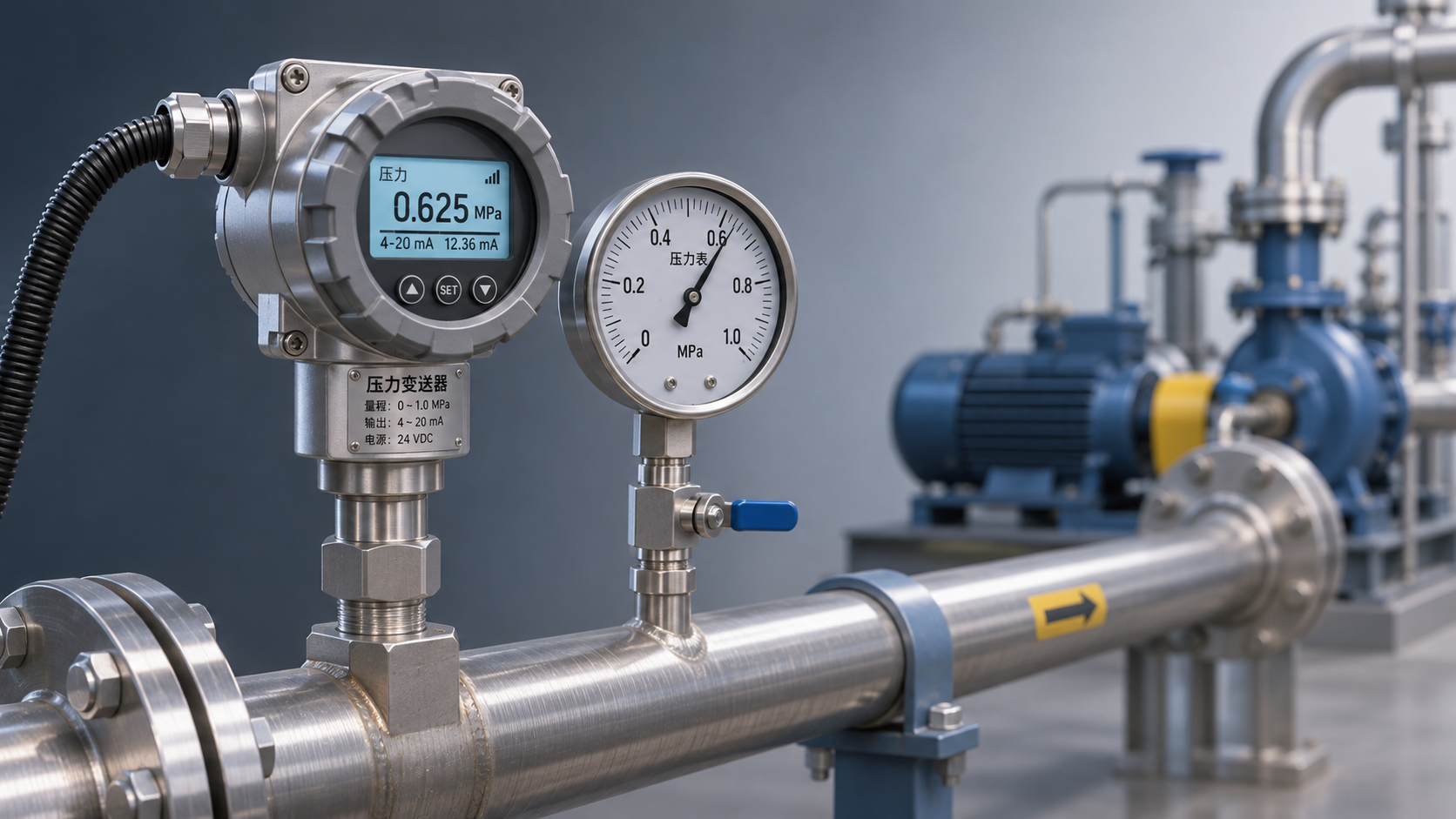
Taking 4-20mA output as an example, 4mA typically corresponds to the lower range limit, and 20mA corresponds to the upper range limit. If the actual current is 12mA, it should theoretically correspond to 50% of the range; if the host computer display deviates significantly from 50%, verify whether the flow meter range, PLC engineering value upper and lower limits, and decimal point settings are consistent.
Establish a Stable Remote Transmission Foundation During Selection
The output type of a remote flow meter should match on-site control requirements. For short-distance, single-point acquisition with mature system interfaces, 4-20mA signals offer relatively strong interference resistance and intuitive fault identification; where multiple instruments are networked, distances are long, or diagnostic parameters need to be read, digital communication methods such as RS485 and Modbus RTU may be prioritized.
For workshops with strong interference, ordinary-output flow meters should not be selected based on price alone. Near variable-frequency motors, high-power contactors, welding equipment, and high-frequency switching power supplies, it is recommended to select products with isolated output, wide-voltage power supply, surge protection, or enhanced communication interference immunity, and to specify electromagnetic compatibility requirements during procurement.
Transmission distance also determines the solution. As analog loop distance increases, cable resistance and the instrument's minimum operating voltage must be calculated; for RS485 buses, the number of nodes, terminating resistors, and branch length require attention. Reserving a 20% to 30% voltage and communication margin during engineering design helps accommodate future line aging and expansion.
Range, Accuracy, and Control System Input Must Be Coordinated
A flow meter range should not operate in an extremely low-flow zone for prolonged periods. Generally, the normal operating flow should fall within 30% to 80% of the instrument range, which both allows room for process fluctuations and reduces relative errors caused by insufficient low-end resolution. The specific ratio should still be based on the flow meter type and product technical specifications.
The analog input module must be clearly configured for 4-20mA and must not be mistakenly set to 0-20mA, 0-10V, or another signal type. For example, treating 4mA as zero current will cause display distortion in the lower-range region and may even trigger low-flow alarms or incorrect interlock actions.
If the flow meter needs to transmit instantaneous flow, totalized flow, temperature, or pressure compensation data simultaneously, register addresses, data types, byte order, and units should be specified at the beginning of the project. Incorrect parameter definitions in digital communication can also appear as “transmission errors,” but the actual cause is inconsistent system integration settings.
Allow Sufficient Power Supply Margin
Two-wire flow transmitters operate on loop power. The power supply voltage, input module voltage drop, and cable voltage drop together determine the actual available voltage at the instrument terminals. If the line is too long, the conductor size is too small, or multiple devices share an unstable power supply, output drift may occur as the load changes.
A stable 24VDC industrial power supply is recommended, with total current calculated based on the number of on-site devices. Long-term power supply load should preferably be controlled within 70% to 80% of rated capacity; for outdoor locations, areas with frequent thunderstorms, or sites with significant grid fluctuations, power lightning arresters, surge protectors, and isolation modules may be added.
During commissioning, measure the supply voltage directly at the flow meter terminals rather than only inside the control cabinet. The voltage difference between the two points indicates the cable voltage drop; when the voltage at the instrument terminals approaches the minimum operating voltage specified for the product, adjust the power supply or shorten the loop promptly.
Standardize Wiring and Grounding to Suppress On-Site Electromagnetic Interference
Signal cable routing is a key factor in reducing remote transmission errors. Flow meter signal cables should be routed separately from power cables whenever possible, especially avoiding 380V power lines, variable-frequency drive output cables, motor cables, and welding machine circuits. A parallel routing distance of more than 300mm is recommended; where conditions permit, metal partitions may be added or independent cable trays may be used.
When signal cables must cross power cables, they should cross vertically at close to 90 degrees to reduce inductive coupling generated by long parallel runs. Within cable ducts and trays, analog, digital communication, and pulse signals should also be placed separately. All low-voltage signal lines must not be indiscriminately bundled together with high-voltage power lines.
For long-distance transmission, shielded twisted-pair cables are recommended as the preferred choice. The twisted-pair structure can reduce common-mode interference, and the shielding layer can mitigate the impact of external electromagnetic fields; however, more shield connections are not necessarily better. Incorrect multipoint grounding may instead create ground loops and introduce new interference currents.
Grounding Should Follow the Principles of Single-Point, Reliable, and Layered Grounding
Instrument enclosure protective grounding, signal shielding grounding, and control cabinet functional grounding serve different purposes and must not simply be interconnected on site. Metal pipelines, the flow meter body, and control cabinets should have reliable protective grounding to reduce personal safety risks and improve interference immunity.
For analog signals, the shielding layer is generally recommended to be grounded at one end on the receiving side to prevent a closed loop formed by grounding at both ends. Whether a digital communication system should be grounded at both ends and whether isolators should be used must be determined comprehensively based on bus length, equipment manuals, and on-site ground potential differences; a single rule of thumb should not be applied.
Grounding conductors should be as short and straight as possible, with an appropriate cross-sectional area, and should not share long, thin grounding branches with high-power equipment. If significant potential differences exist between different areas of the control cabinet, interference paths can be interrupted through signal isolators, isolated power supplies, or isolated communication modules to improve remote transmission stability.
Maintain Data Reliability Through Commissioning, Calibration, and Maintenance
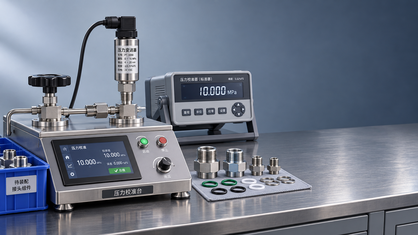
After installation of a remote flow meter, conduct a three-point verification of “instrument output value, measured line value, and system display value.” Using a standard ammeter or process calibrator to check key points such as 4mA, 8mA, 12mA, 16mA, and 20mA can quickly determine whether the error originates from the transmitter, wiring, or PLC input module.
For RS485 communication, confirm the device address, baud rate, parity method, stop bits, and register definitions item by item. For example, 9600bps, 8 data bits, no parity, and 1 stop bit are only a common combination and are not the default settings of all devices; inconsistency in any parameter may cause intermittent disconnection or abnormal data parsing.
On-site acceptance should not only check whether data is consistent at a specific moment. It should also observe curve performance during equipment start-stop operations, load changes, and operation of high-interference equipment. Continuously recording trend data for 24 hours to 72 hours makes it easier to identify hidden issues such as short-duration fluctuations, communication reconnections, or power supply variations.
Establish an Implementable Periodic Inspection Mechanism
It is recommended to include remote flow meters in the equipment inspection plan. Under normal operating conditions, check terminal tightness, shielding integrity, grounding condition, and cable jackets every 3 months; in high-temperature, humid, corrosive, or high-vibration environments, shorten the inspection interval as appropriate and focus on junction box sealing and cable entry aging.
The calibration interval should be determined according to metrological requirements, medium characteristics, and frequency of use. For flow meters used in trade settlement, batch batching, or critical process control, verification may be conducted according to an annual plan; for applications where the medium is prone to scaling, contains particles, or experiences major operating-condition fluctuations, process comparison and zero-point checks should also be increased.
Maintenance records should retain the instrument number, range, output type, power supply voltage, loop current, communication parameters, and abnormality handling results. After establishing traceable records, similar faults can be located more quickly, and accurate on-site references can be provided for subsequent expansion, replacement, and non-standard customization.
Troubleshoot Segment by Segment Along the Link When Abnormalities Occur
When host computer flow data is abnormal, first check whether the local flow meter display is normal; if the local display is normal but the remote end is abnormal, measure the output signal, then inspect the intermediate junction box, cable, and control cabinet input terminal. Confirming each segment from the source to the receiving end in this way is more efficient than directly replacing the instrument.
If the 4-20mA loop current is stable but the system engineering value is abnormal, focus on checking the PLC channel type, range conversion formula, filtering time, and alarm thresholds. If the loop current itself fluctuates, continue investigating the power supply, interference sources, grounding, and sensor operating conditions rather than only adjusting software filtering.
When configuring remote flow meters, users in Shaanxi may provide the on-site medium, pipe diameter, pressure and temperature, transmission distance, power supply conditions, control system model, and interference source information to the technical staff of Xi'an Shenghongchuang Instrumentation Co., Ltd. A professional team can then complete selection verification, wiring recommendations, and commissioning support to establish a more stable and reliable industrial flow measurement and control link.
Related Recommendations
 Ceramic-Core vs. Oil-Filled Pressure Transmitters: How to Choose Based on Corrosion Resistance and Overload Capacity
 How should the wetted parts of a 316L pressure transmitter be inspected for corrosive media?
 What Causes Unstable Readings on a Pressure Transmitter with an LCD Display?
 What usually affects the lead time for a custom pressure transmitter?