


News Center
—— NEWS CENTER ——
Xi'an Shenghongchuang Instrument Co., Ltd.
Contact: Mr. Zhang
Mobile: 15529283736
Email: shc-sensor@qq.com
Address: Fortune Building, Sanqiao Street, Xixian New Area, Xi'an, Shaanxi Province
Unstable readings on an LCD pressure transmitter may be related to process pressure fluctuations, power supply interference, or wiring faults. When troubleshooting, first determine whether the pressure is actually changing, then check the instrument’s electrical connections, installation conditions, and parameter settings. Do not conclude that the sensor is damaged based solely on fluctuating display digits.
I. First distinguish actual pressure fluctuations from instrument abnormalities
Observe reading changes alongside equipment operating conditions
A pressure transmitter displays the pressure near the measuring point. Pump start-up and shutdown, changes in valve opening, reciprocating compressor operation, and changes in the flow rate of the medium in the pipeline can all cause periodic or sudden pressure fluctuations. Such changes reflect actual operating conditions and do not necessarily indicate an instrument fault.
Record when the fluctuations occur, their amplitude and period, and compare them with the operation of pumps, valves, and motors. For example, if the reading fluctuates within seconds of a pump starting, first check for start-up surges and changes in pipeline pressure rather than directly adjusting the instrument zero point.
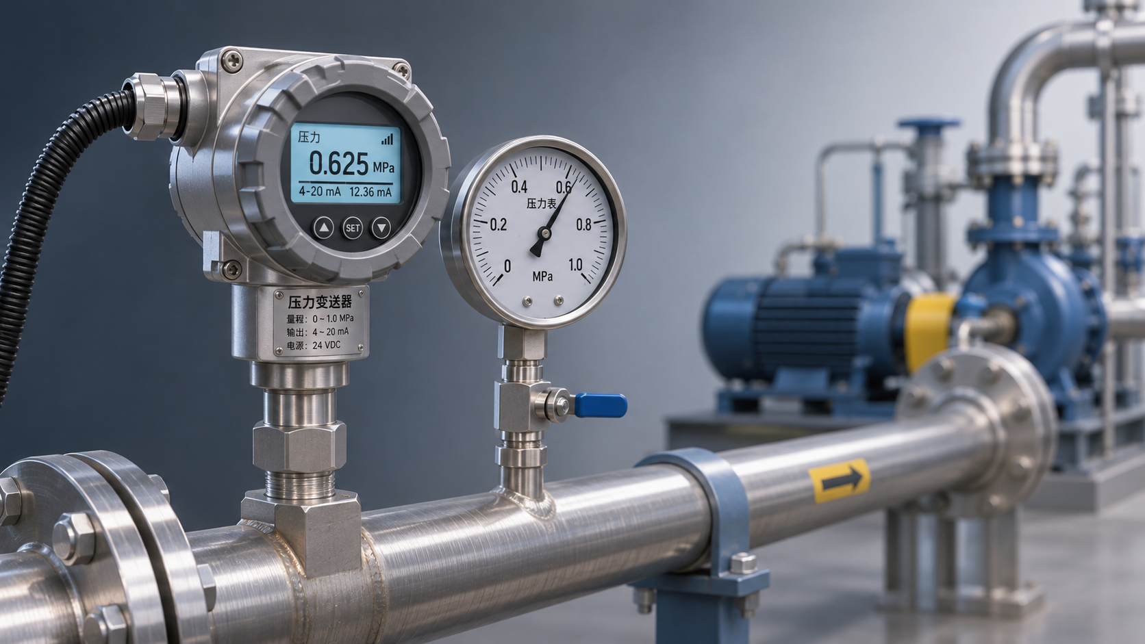
Where conditions permit, connect a standard pressure gauge with a suitable range and accuracy at a nearby measuring point for comparison. If both instruments change in sync, the process system usually needs further inspection. If the standard gauge remains stable while the LCD reading continues to fluctuate, focus on the transmitter and its installation and electrical conditions.
When comparing measurements, also consider the response speed, damping settings, and installation locations of the two instruments. A pointer gauge responds more slowly; even if it appears stable, this alone does not prove that there are no rapid pressure pulsations in the pipeline.
What observations are useful for diagnosis
Record the pressure unit, range, displayed value, and operating conditions together. For example, a 0–1 MPa instrument fluctuating between 0.498 and 0.502 MPa under stable operating conditions has a fluctuation range of 0.004 MPa. Whether this is abnormal must still be assessed in light of the instrument’s accuracy, resolution, and application requirements.
If the reading changes only in the last displayed digit and the control system is operating normally, first check the display resolution and the allowable deviation for the application. When many digits are displayed, even minor measurement noise may appear as fluctuating digits.
If the displayed value suddenly drops to zero, reaches full scale, shows an error code, or the screen flickers, document what is happening on site and consult the manual for the relevant model. These symptoms may involve the power supply, wiring, overrange conditions, or an internal fault and should not be treated simply as normal pressure fluctuations.
II. Check the power supply, wiring, and electromagnetic interference
Start with the power supply and loop connections
Insufficient or fluctuating supply voltage, loose terminals, damaged cables, and damp connectors can all affect the LCD display and signal output. For two-wire 4–20 mA instruments in particular, check the power supply, load resistance, and wire voltage drop in the loop, and confirm that the actual voltage at the transmitter terminals meets the product requirements.
Voltage measurements should be carried out by qualified personnel using suitable instruments and in accordance with site safety requirements. Do not measure only the power supply’s no-load voltage; also measure the voltage at the transmitter terminals while the equipment is operating normally and check whether voltage fluctuations coincide with changes in the reading.
Before checking wiring, follow site procedures to disconnect the power and confirm that it is safe to proceed. Check that the terminals are secure, the copper conductors are not oxidized, the sealed cable glands have not let in water, and the shielding and grounding connections meet the manufacturer’s requirements. After tightening the connections or replacing cables, restore power and verify operation.
Check for interference from variable-frequency equipment and wiring
Variable-frequency drives, welding machines, high-power motors, and their cables can be sources of strong interference. Readings may change in sync with equipment start-up and shutdown if signal cables run parallel to power cables over long distances, or if grounding or shielding does not meet requirements.
First compare when the interference occurs with equipment operation, then check whether signal cables are routed separately from power cables and whether the shielding and grounding methods meet the requirements of the instrument and system design. Grounding requirements may differ between devices, so do not add grounding points without first confirming that this is appropriate.
If the LCD display is stable but the value on the PLC or digital display instrument fluctuates, continue by checking the transmitter output loop, input module, range mapping, and control system filter settings. The processing paths for the LCD display and remote signal vary by model. If their behavior differs, analyze the wiring diagram.
III. Check installation conditions and the condition of the medium
Check for pressure pulsations, vibration, and pressure connections
Equipment such as plunger pumps and reciprocating compressors can generate pressure pulsations. A transmitter installed near a pump outlet may therefore show pronounced fluctuations. First confirm whether the fluctuations affect the process, then assess whether to install a buffer device or adjust the pressure connection location based on the medium, pressure rating, and response requirements.
A buffer device, damping orifice, or impulse line may reduce the effect of rapid pulsations on readings, but can also delay the response to pressure changes. For measuring points used for interlocks, protection, or fast control, process and instrumentation personnel should confirm the arrangement together. Do not reduce response speed simply to make the displayed value appear stable.
Pipeline vibration, loose mounting brackets, or mechanical impacts from equipment may also affect measurements. At locations with strong vibration, check the fasteners, connection method, and product vibration resistance requirements. If necessary, adjust the installation arrangement in accordance with the applicable design specifications.
Pressure port blockage and temperature effects
Particles, crystallized material, or viscous deposits in the medium may block the pressure port or impulse line, causing readings to respond slowly, fluctuate, or fail to reflect the actual pressure. Before cleaning, isolate and depressurize the system in accordance with procedures, and confirm the medium’s temperature and hazards.
High or low temperatures and rapid temperature changes may also affect measurement performance. Refer to the product’s permitted medium and ambient temperature ranges and installation requirements. Condensation, icing, or seal failure may cause additional problems and should be assessed in light of the properties of the medium on site.
Use suitable instruments for temperature and pressure measurement. For example, CWDZ16 Integrated Industrial Digital Display Temperature Transmitter, Made in China is used for industrial temperature measurement and can be equipped with an LCD display and various mounting options. It cannot replace a pressure transmitter. When selecting an instrument, verify the temperature sensing element, temperature range, and output type.
IV. Verify the parameters and arrange calibration
Range, damping, and display settings
If the selected range is too wide, actual pressure changes account for only a small portion of the full scale, making display resolution and measurement error more likely to affect the assessment. If the range is too narrow, pressure surges may cause an overrange condition. Selection should take into account normal operating pressure, maximum pressure, transient surges, and the product’s permissible overload capacity.
For instruments with adjustable damping, increasing the damping appropriately will generally make the display more stable, but will also slow the response. For example, changing the damping time from 1 second to 3 seconds may improve the display of rapid fluctuations. The actual effect should be verified against the instrument manual and under site conditions.
Also check the pressure unit, decimal places, zero point, and output range. For a standard linear 4–20 mA output, 4 mA and 20 mA typically correspond to the lower and upper limits of the configured range, respectively. The specific mapping and fault current rules should be confirmed against the device configuration and manual.
When to arrange inspection or replacement
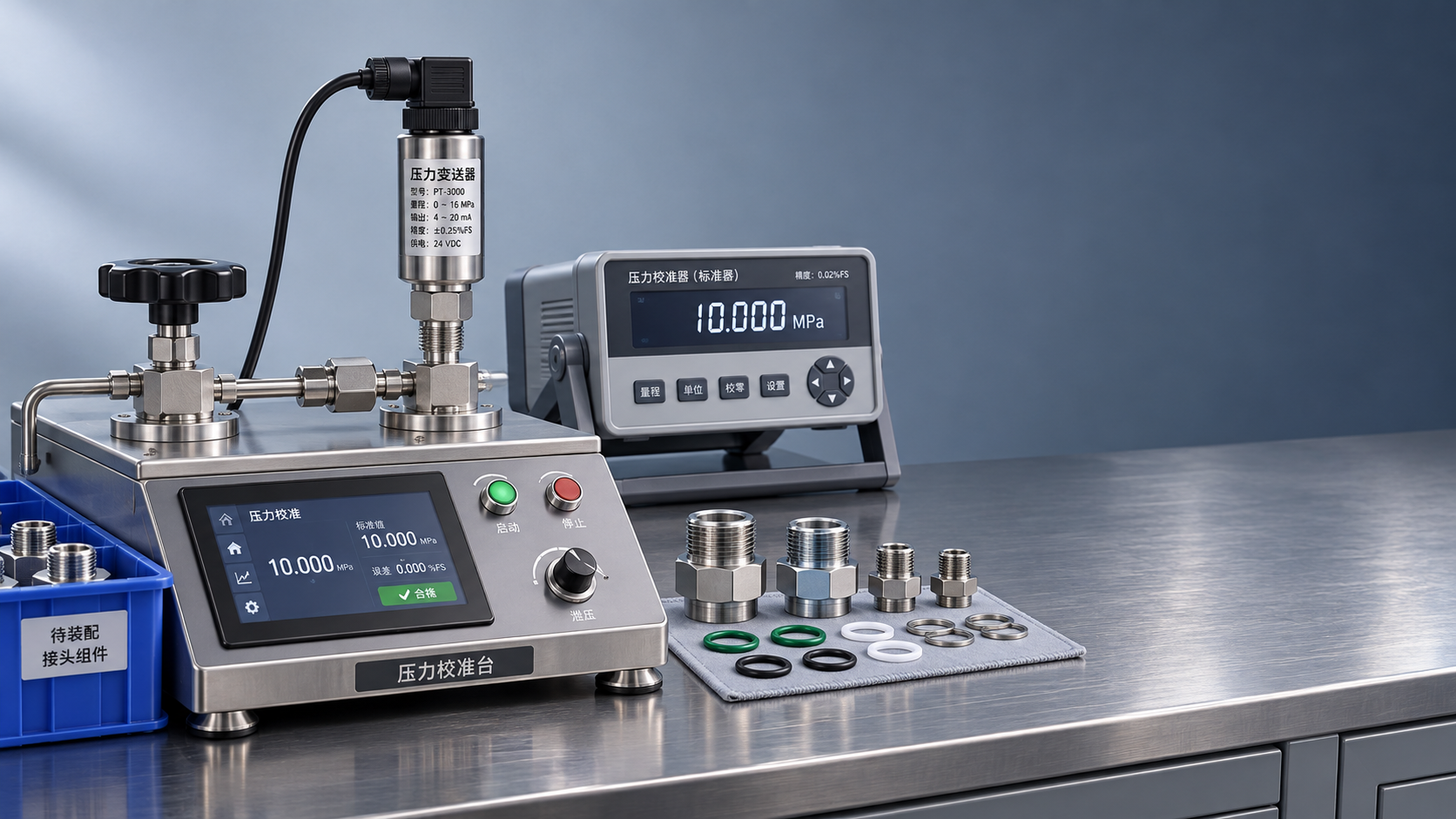
If the instrument continues to fluctuate under a stable pressure source after process fluctuations, power supply and wiring, and installation issues have been ruled out, or if the zero point repeatedly drifts or the display behaves abnormally, arrange professional calibration. Calibration should cover the commonly used operating range and use suitable standard equipment. Do not make a judgment based solely on a single-point reading.
If there is clear evidence of liquid ingress, damage to the housing or diaphragm, or abnormal behavior after an overpressure event, stop using the instrument and have qualified personnel assess whether it should be repaired or replaced. In hazardous areas, follow the relevant safety requirements. Do not open the housing while energized or modify explosion-proof construction without authorization.
Xi'an Shenghongchuang Instrumentation Co., Ltd. provides sales and technical services for sensors, transmitters, and supporting instruments. If you encounter unstable readings, collect the instrument model, range, power supply method, medium, installation location, and fluctuation records, then contact technical personnel for targeted troubleshooting and verification of the instrument selection.
Related Recommendations
 What Causes Unstable Readings on a Pressure Transmitter with an LCD Display?
 What usually affects the lead time for a custom pressure transmitter?
![]() Shelly launches the Presence Gen4 millimeter-wave presence sensor, priced at $84.99 in North America
![]() Canrui Technology’s 3D Hall sensors are now in mass production and shipping, targeting perception applications in embodied intelligence