News Center
—— NEWS CENTER ——
Xi'an Shenghongchuang Instrument Co., Ltd.
Contact: Mr. Zhang
Mobile: 15529283736
Email: shc-sensor@qq.com
Address: Fortune Building, Sanqiao Street, Xixian New Area, Xi'an, Shaanxi Province
Why Differential Pressure Sensors Are Used in Residential Fresh Air Systems
The core objective of residential fresh air systems is to meet indoor ventilation requirements while minimizing fan energy consumption, noise, and maintenance costs. Whether for residential total heat recovery ventilators, centralized fresh air systems in villas, or fresh air handling units in public buildings such as office buildings, schools, and hotels, the airflow rate in ducts, filter resistance, and supply-exhaust air balance change over time during operation. Residential differential pressure sensors can convert these changes into readable and controllable differential pressure signals.
In duct airflow measurement applications, differential pressure sensors are typically used with Pitot tubes, averaging tubes, or airflow measurement devices. By measuring dynamic pressure or pressure differential, the controller can calculate air velocity and airflow rate and regulate the speed of variable-frequency fans accordingly. For filter monitoring, the degree of dust accumulation is determined by comparing the pressure difference upstream and downstream of the filter. When resistance reaches the set value, the system indicates that the filter element should be replaced.
Selection should not be based solely on “duct size” or simply on choosing a wide measurement range. The duct cross-sectional area determines the average air velocity, which determines the measurable dynamic pressure; system resistance, installation location, control purpose, and allowable error together determine the measurement range, accuracy, overload capacity, and output method. If the range is too large, resolution in the low-pressure range will be insufficient; if the range is too small, it may be exceeded due to startup surges, filter blockage, or fan abnormalities.
For residential fresh air projects, a more practical approach is to first identify the measurement target, then calculate the differential pressure under normal operating conditions and the maximum possible differential pressure, and finally match the sensor range and accuracy class. Xi'an Shenghongchuang Instrumentation Co., Ltd. can provide residential differential pressure sensors and supporting pressure measurement solutions based on duct dimensions, design airflow, fan static pressure, filter section configuration, and control interfaces.
Calculating Differential Pressure Range Based on Duct Parameters
First Calculate Air Velocity from Airflow and Cross-Sectional Area
Duct air velocity is the basis for airflow measurement selection. The cross-sectional area of a rectangular duct can be calculated by multiplying width by height, while that of a circular duct can be calculated as πD²÷4. Airflow is commonly expressed in m³/h. After converting it to m³/s and dividing it by the effective duct cross-sectional area, the average air velocity can be obtained. In actual projects, the clear internal cross-sectional area of the duct should be used, while considering the impact of local components such as dampers, silencers, and duct elbows on airflow field uniformity.
For example, a residential fresh air unit has a design airflow of 500m³/h and is connected to a main supply air duct measuring 250mm×200mm, with a duct cross-sectional area of approximately 0.05m². After converting 500m³/h to 0.139m³/s, the average air velocity is approximately 2.78m/s. The dynamic pressure generated by such low-velocity ducts is relatively low. If a high-range 0~1000Pa product is selected, the effective utilization rate of the control signal is often low.
Air velocity in branch ducts of residential fresh air systems is typically around 2m/s to 4m/s, while main ducts commonly operate at 3m/s to 6m/s; main ducts in commercial premises or equipment rooms may reach 6m/s to 8m/s. The lower the air velocity, the more attention should be paid to the zero stability, low-range accuracy, and resolution of the differential pressure sensor. If the system is mainly used for constant airflow control, the differential pressure under normal operation should preferably fall within the middle-to-upper effective range of the sensor.
Estimating the Airflow Measurement Range Using Dynamic Pressure
Air dynamic pressure can be estimated using the formula q=0.6V², where q is dynamic pressure in Pa and V is air velocity in m/s. This formula is suitable for engineering estimates for air at normal temperature and pressure. At an air velocity of 2m/s, the dynamic pressure is approximately 2.4Pa; at 4m/s, approximately 9.6Pa; and at 6m/s, approximately 21.6Pa.
A Pitot tube measures the difference between total pressure and static pressure and can theoretically be used to calculate air velocity. However, insufficient straight duct length, probe orientation deviation, or local turbulence can affect measurement results. For residential fresh air ducts, pressure tapping points are recommended to be installed in straight duct sections with relatively stable airflow, away from elbows, tees, dampers, and transitions. In general, installation conditions with at least 5 equivalent diameters upstream and at least 2 equivalent diameters downstream should be considered as a priority.
The selected range is usually not directly equal to the calculated dynamic pressure; allowance should be reserved for fan speed control, system residual pressure, and abnormal operating conditions. If the normal dynamic pressure is approximately 10Pa and the maximum operating condition is expected not to exceed 25Pa, a 0~50Pa or 0~100Pa range may be selected. If the normal dynamic pressure is already close to 35Pa and a wide airflow adjustment range is required, 0~100Pa is more reliable. For bidirectional supply-exhaust air balance monitoring, positive and negative pressure ranges should also be selected according to the actual signal direction.
Range and Accuracy Selection for Different Measurement Objectives
Airflow Control Should Prioritize Low-Pressure Performance
When used for duct airflow control, differential pressure signals are generally small. Taking a 0~50Pa sensor as an example, if the accuracy is ±1% of full scale, the allowable error is approximately ±0.5Pa; when the actual measured value is only 5Pa, this error accounts for approximately 10%. Therefore, low-air-velocity measurement should not blindly increase the full-scale range. Differential pressure sensors with a low range and high stability are more suitable.
For residential fresh air systems used for general airflow trend monitoring and fan interlocking, products with full-scale accuracy of ±1%FS to ±2%FS may be selected. For constant airflow, supply-exhaust air balance, or applications requiring more stable air velocity feedback, accuracy of ±0.5%FS to ±1%FS is recommended, with particular attention to zero drift, repeatability, and long-term stability indicators.
It should be noted that airflow and differential pressure are not linearly related; airflow is proportional to the square root of differential pressure. When differential pressure is low, even a slight zero offset can be amplified into a significant airflow calculation error. Therefore, the controller should have square-root calculation capability or adopt control logic with airflow compensation. After installation, commissioning and verification should also be performed in combination with actual airflow.
Filter Clogging Monitoring Should Be Selected Based on Final Resistance
Filter differential pressure monitoring differs from airflow monitoring. The focus is not on dynamic pressure of only a few Pa, but on the resistance change between clean and clogged filter conditions. The initial resistance of common coarse filters may range from 20Pa to 50Pa, while that of medium-efficiency filters may be approximately 50Pa to 100Pa. Specific values should be based on the specifications provided by the filter manufacturer and the system design final resistance.
If the initial filter resistance is approximately 30Pa, the recommended replacement differential pressure setting is 100Pa, and the differential pressure at maximum fan static pressure and under abnormal conditions may exceed 150Pa, a 0~250Pa range can be prioritized. If the design final resistance of a high-efficiency filter section is 250Pa to 400Pa, a 0~500Pa or 0~1000Pa range should generally be considered to prevent the sensor from operating near full scale for extended periods.
Extremely high accuracy is not necessarily required for filter differential pressure sensors, but clogging resistance, long-term zero stability, and alarm output reliability should be emphasized. In residential projects, ±1%FS or ±2%FS can generally meet filter replacement reminder requirements. For unattended equipment rooms or building automation systems, outputs such as 4~20mA, 0~10V, and RS485 can be selected for connection to DDC, PLC, or intelligent control platforms.
Technical Parameters to Verify Beyond Accuracy
Distinguishing Full-Scale Accuracy, Overall Accuracy, and Resolution
When purchasing differential pressure sensors, the accuracy designation method should be clarified. ±1%FS means that the error is calculated based on full scale. For a 0~100Pa range, the allowable error is approximately ±1Pa; for a 0~50Pa range, it is approximately ±0.5Pa. With the same nominal ±1%FS, low-range products have a smaller absolute error when measuring small differential pressures.
In addition to basic accuracy, temperature drift can also affect the long-term operation of fresh air equipment. In equipment rooms, above ceilings, or in areas with significant winter-summer temperature differences in northern regions, ambient temperature changes may cause zero offset. For applications that measure small differential pressures below 10Pa year-round, products with low temperature drift and good zero stability should be prioritized, and zero-point checks should be carried out during installation and commissioning.
Resolution determines whether the sensor can detect small changes, while response time affects the tracking performance of variable-frequency fan control. Residential fresh air applications generally do not require extremely fast millisecond-level response. Appropriate software filtering helps reduce signal fluctuations caused by airflow pulsation. However, excessive filtering time causes control lag, so it should be set comprehensively according to the fan adjustment cycle and on-site airflow stability.
Output Signals and Installation Accessories Also Affect Final Performance
For newly constructed building automation projects, 4~20mA signals offer strong anti-interference capability and are suitable for applications with long transmission distances and complex electromagnetic environments; 0~10V output is easy to connect and suitable for equipment control over short distances; RS485 communication facilitates centralized multipoint data acquisition and remote parameter viewing. The output method should match the input interface of the existing controller to avoid adding signal conversion modules later.
During installation, the high-pressure and low-pressure impulse tubes must not be connected in reverse. When measuring filter differential pressure, connect the high-pressure side to the upstream side of the filter and the low-pressure side to the downstream side; when measuring duct dynamic pressure, connect according to the markings on the Pitot tube or averaging tube. Impulse tubes should be as short and straight as possible, avoiding kinks, flattening, water accumulation, and air leakage, otherwise response delays or distorted readings may result.
The sensor body should preferably be installed in a location that is convenient for maintenance, subject to minimal vibration, and protected from condensate. For outdoor fresh air sections or high-humidity areas, the protection rating, condensation risk, and dust protection measures for pressure tapping ports should be considered. After installation is completed, signals should be checked respectively at low, rated, and high fan speeds to confirm that the zero point, direction, range, and alarm thresholds all meet control requirements.
Practical Steps for Selecting Differential Pressure Sensors for Residential Fresh Air Systems
Step 1: Define the measurement purpose: measuring duct air velocity, controlling supply-exhaust air balance, monitoring filter clogging, or maintaining positive or negative room pressure. The differential pressure ranges for different purposes vary considerably, and one range cannot cover all locations. Step 2: Provide basic parameters such as design airflow, duct dimensions, total fan pressure, and initial and final filter resistance.
Step 3: Calculate or confirm the normal differential pressure, maximum differential pressure, and minimum effective differential pressure. It is generally recommended that the normal operating value fall within 30% to 80% of the sensor range, with allowance reserved for maximum operating conditions. Step 4: Determine the accuracy class according to control accuracy. Ordinary alarms may use ±1%FS to ±2%FS, while constant airflow and low-pressure balance control should prioritize models with lower ranges and higher stability.
Step 5: Confirm the output, power supply, installation method, interface dimensions, impulse tube material, and environmental conditions. For projects requiring local display and alarm point setting, differential pressure control instruments with digital display and relay output may be selected. For projects connected to building automation systems, the analog signal range, communication protocol, and controller range settings should be confirmed.
Leveraging the production and technical capabilities of Shaanxi Qinkong Sensor Technology Co., Ltd., Xi'an Shenghongchuang Instrumentation Co., Ltd. can provide differential pressure sensors, differential pressure transmitters, and customized measurement and control solutions for residential buildings, commercial complexes, school and hospital supporting areas, and various ventilation equipment. By submitting duct cross-sectional dimensions, design airflow, filter parameters, installation location, and control signal requirements, you can obtain targeted selection recommendations for the corresponding range, accuracy, output method, and installation accessories.
Related Recommendations
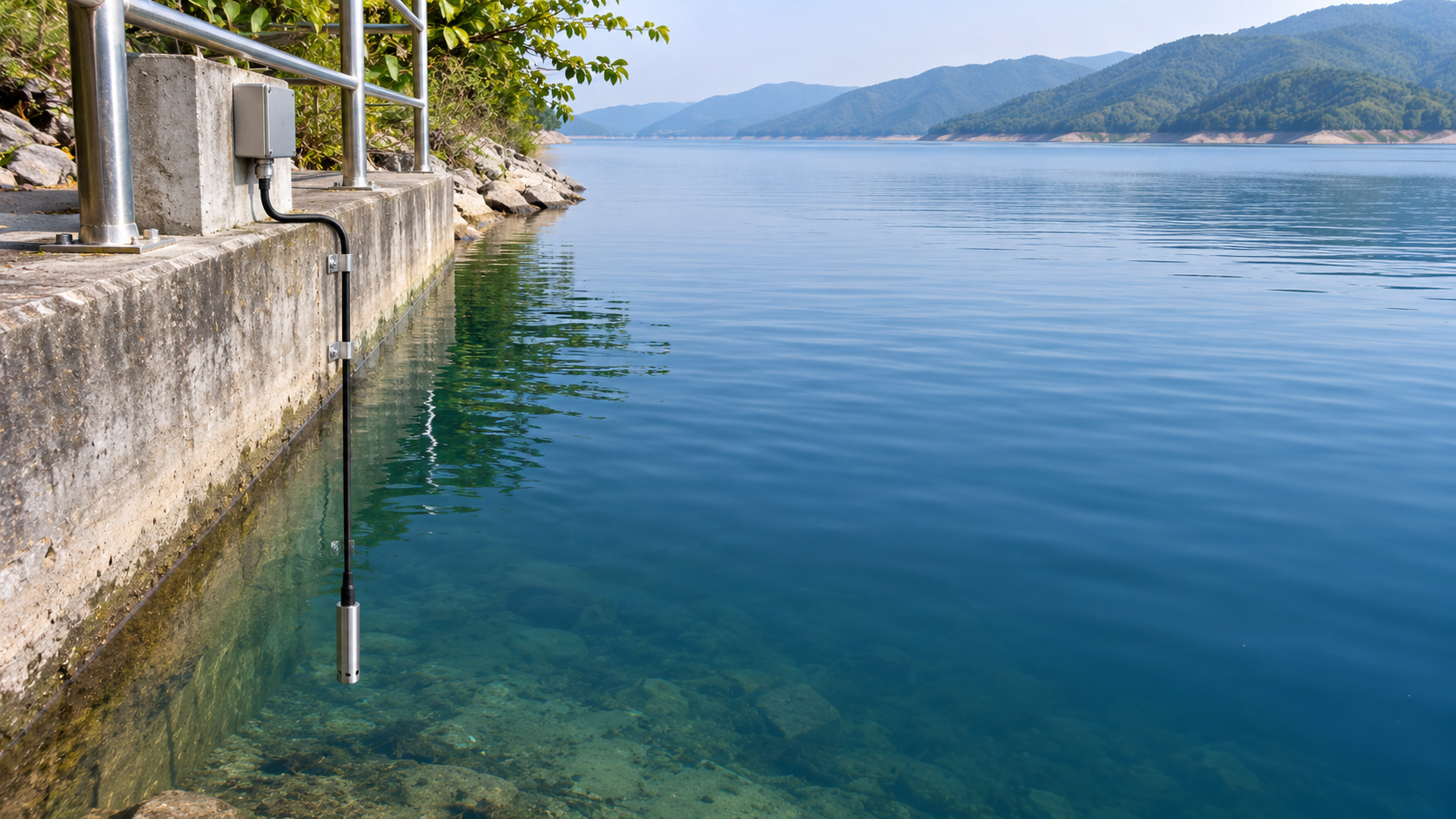
 What Can Hydraulic Pressure Transmitters Measure? Applications from Reservoir Water Levels to Pipeline Pressure
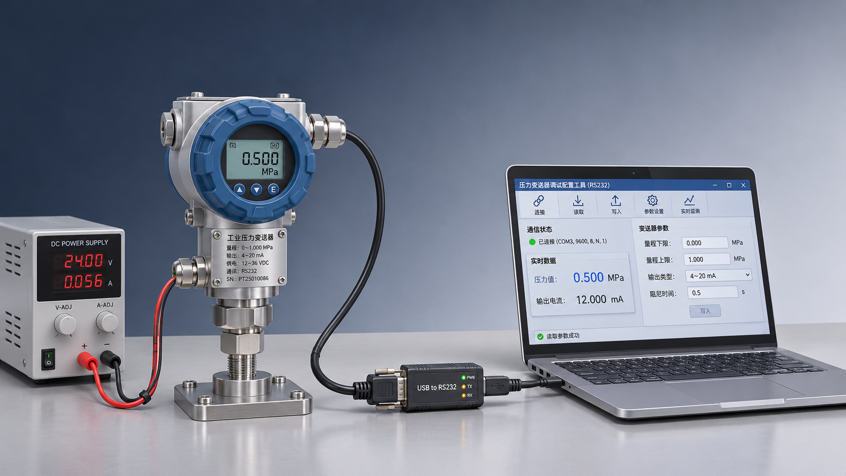
 Connecting an RS232 Pressure Transmitter to a Host Computer: Serial Port Parameters and Communication Troubleshooting
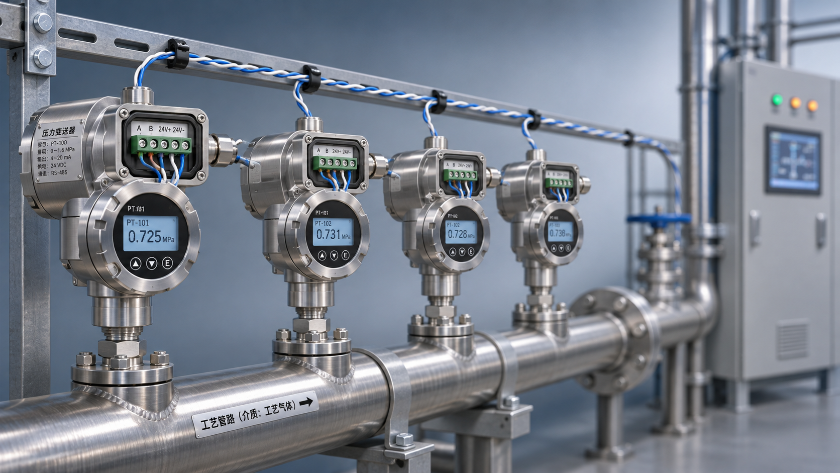
 RS485 Pressure Transmitter Multi-Drop Networking: How to Set the Terminating Resistor and Device Addresses?
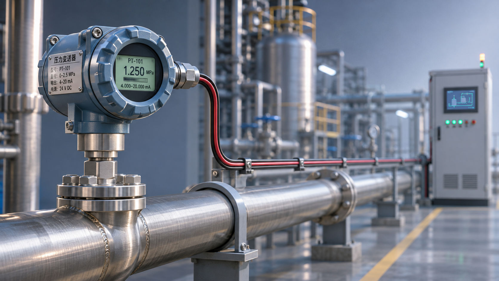
 How Does a HART Pressure Transmitter Use an Overlay Signal for Remote Configuration?