


News Center
—— NEWS CENTER ——
Xi'an Shenghongchuang Instrument Co., Ltd.
Contact: Mr. Zhang
Mobile: 15529283736
Email: shc-sensor@qq.com
Address: Fortune Building, Sanqiao Street, Xixian New Area, Xi'an, Shaanxi Province
How to Set Alarm Points for Differential Pressure Sensors with Relay Outputs
Differential pressure sensors with relay outputs integrate differential pressure measurement, digital display, and switching control. They are commonly used for filter clogging monitoring, fan air pressure control, cleanroom differential pressure monitoring, liquid level differential monitoring, and pipeline flow status determination. Properly setting alarm points enables equipment to send signals promptly when differential pressure becomes abnormal and activate audible and visual alarms, fans, valves, or control systems.
Alarm parameters should not be entered arbitrarily based solely on experience. They should be determined comprehensively according to the actual measuring range, normal operating differential pressure, allowable fluctuation range, equipment limit, and relay control logic. If the setpoint is too low, minor on-site fluctuations may trigger frequent alarms; if it is too high, abnormal conditions such as filter element clogging, fan failure, or loss of differential pressure control may be missed.
The menu names of different models of intelligent differential pressure sensors vary slightly. Common parameters include high alarm value, low alarm value, hysteresis, alarm delay, relay operating mode, and normally open/normally closed status. The following uses a two-relay-output differential pressure sensor commonly used in industrial sites as an example to explain the principles and commissioning methods for setting alarm points.
I. Confirm the Measuring Range and Normal On-Site Differential Pressure Before Setting
The Measuring Range Should Cover Both Normal Values and the Abnormal Upper Limit
First, confirm the sensor measuring range, such as 0–1kPa, 0–5kPa, -1–1kPa, or 0–10kPa. The actual normal differential pressure should preferably fall within 30%–70% of the full scale, which ensures resolution while reserving sufficient margin for sudden fluctuations.
For example, in air handling unit filter monitoring, if the initial differential pressure is approximately 120Pa and the allowable differential pressure before filter replacement is 450Pa, a differential pressure sensor with a 0–1kPa range may be selected. If a 0–10kPa range is selected, although it will not exceed the measuring range, the display resolution and control accuracy in the low differential pressure range will usually be affected.
For positive and negative differential pressure applications, such as differential pressure control between adjacent cleanroom areas, the connection direction of the high-pressure and low-pressure ports should be confirmed. If connected in reverse, the displayed value may be negative, and the relay alarm logic will also be opposite to expectations. The on-site impulse tubing connections should be verified before commissioning.
It Is Recommended to Record Stable Operating Data First
After the equipment has operated stably for more than 30 minutes, continuously record the differential pressure values. It is recommended to collect at least 10 sets of data and calculate the normal fluctuation range. For example, if the normal value fluctuates between 180Pa and 230Pa, the alarm point should not be set close to 230Pa; a reasonable margin should be reserved according to process risk.
II. Logic for Setting High and Low Alarm Points
High Alarm Is Used for Differential Pressure Overlimit Protection
The high alarm value is usually denoted as HI, AH, or SP1. When the actual differential pressure reaches or exceeds this setpoint, the relay operates according to the configured logic. In filter applications, a high alarm generally indicates increased resistance and serves to notify maintenance personnel to inspect or replace the filter element.
The high alarm point should be determined according to the maximum differential pressure allowed by the equipment, rather than being set directly at the sensor full scale. For example, if the sensor range is 0–1kPa and the maximum differential pressure permitted by the process is 500Pa, the high alarm can initially be set at 450Pa–480Pa instead of 1000Pa.
If graded response is required on site, two relays can be used to set a pre-alarm and an alarm. The first relay operates at 400Pa to remind personnel of maintenance; the second relay operates at 500Pa for interlocking load reduction, shutdown, or transmission to the PLC. It is recommended to maintain an interval of at least 50Pa between the two alarm levels to prevent frequent switching of both relays within the same fluctuation range.
Low Alarm Is Used to Detect Insufficient or Reversed Differential Pressure
The low alarm value is usually denoted as LO, AL, or SP2. It is suitable for monitoring conditions such as fan stoppage, belt breakage, impulse tubing disconnection, door opening, or system leakage. When the actual differential pressure falls below the set threshold, the relay outputs an alarm signal.
For example, if the normal differential pressure of a supply air system is 1.5kPa–2.0kPa and a value below 1.0kPa may affect air supply capacity, the low alarm point can be set to 1.0kPa or 1.1kPa. If actual fluctuations reach ±0.15kPa, the alarm point should avoid the normal lower limit to prevent false alarms during start-up and shutdown switching.
For cleanroom differential pressure, the low alarm is often more important than the high alarm. If the design differential pressure is 20Pa and normal fluctuations are 15Pa–25Pa, the low alarm can be set to 12Pa–15Pa; the specific value should also comply with on-site cleanliness management standards and process requirements.
Typical Alarm Parameter Example
After the alarm points have been set, they should be verified under different operating conditions, including equipment operation, shutdown, loading, and unloading. Seeing normal values only under static conditions does not mean that the alarm logic is reliable during actual production.
III. Hysteresis and Delay Settings Determine Alarm Stability
Hysteresis Prevents Relay Chatter
Hysteresis, also known as a dead band or reset differential, is the difference between the alarm actuation value and the recovery value. Taking a high alarm of 450Pa and a hysteresis of 30Pa as an example, the relay operates when the differential pressure rises to 450Pa and recovers only when it drops below 420Pa. This prevents repeated relay energization when the value fluctuates around 450Pa.
If the hysteresis is set too small, such as only 1Pa–2Pa, air pressure pulsation, electromagnetic interference, or changes in display resolution on site may cause frequent relay operation; if the hysteresis is too large, alarm recovery will be too slow. In general, it can be set to 1.5–2 times the normal fluctuation amplitude.
For pulse systems with large differential pressure fluctuations, priority should be given to checking the pressure tapping location, liquid accumulation in impulse tubing, filter damping, and mechanical vibration. Increasing hysteresis should not be relied on entirely to conceal installation problems; otherwise, although the alarm may not chatter, the actual measurement response may be distorted.
Delay Parameters Should Match the Process Cycle
Alarm delay refers to the time for which the differential pressure must continuously exceed the set threshold before the relay operates. Common settings are 1 second, 3 seconds, 5 seconds, or 10 seconds. For differential pressure fluctuations at the instant of fan start-up, a delay of 3–10 seconds may be set; for applications with stringent safety interlock requirements, the delay should be shortened and confirmed by the process.
When setting delays, distinguish between “actuation delay” and “recovery delay.” Actuation delay can filter out short-term interference, while recovery delay can prevent repeated cycling immediately after the condition has recovered. Where equipment protection is involved, relay delay settings must be checked consistently against the PLC program, variable-frequency drive logic, and on-site interlock sequence.
If the sensor supports digital filtering, the filtering time and alarm delay will also be cumulative. For example, if the filter is set to 2 seconds and the actuation delay is set to 5 seconds, the actual alarm response may approach 7 seconds. Timing verification should be conducted using actual pressure changes during commissioning.
IV. Confirmation of Relay Output Mode and On-Site Wiring
Clarify Normally Open, Normally Closed, and De-energized Protection Requirements
Relay outputs generally provide normally open contacts, normally closed contacts, and a common terminal. Whether the circuit is closed or opened during an alarm depends on the relay operating mode and actual wiring method. For general indication purposes, wiring can follow conventional alarm logic; for critical protection, a de-energized alarm approach is recommended so that sensor power loss or line disconnection can also be identified by the control system.
Before setting, confirm whether the relay is configured for “upper-limit energization, lower-limit energization,” or “window control.” Window control is suitable for processes requiring differential pressure to remain within a certain range: an alarm is triggered below the lower limit and above the upper limit, and the equipment status is normal only when it is within the set range.
Relay contact capacity must meet load requirements. Sensor relays are generally suitable for outputting control signals and should not directly drive high-power motors, electric heaters, or high-current solenoid valves. When the load exceeds the contact-rated voltage or current, an interposing relay, contactor, or PLC output module should be used for isolated driving.
Perform On-Site Commissioning According to “Simulation, Observation, and Verification”
During commissioning, a standard differential pressure source, a manual pressure pump, or actual operating conditions can be used to gradually vary the differential pressure value. Observe whether the displayed value, relay indicator, PLC input status, and actuator feedback are consistent. At a minimum, four points should be tested: high alarm actuation, high alarm recovery, low alarm actuation, and low alarm recovery.
Test results should be documented, including sensor number, measuring range, setpoint, hysteresis, delay, contact status, test date, and commissioning personnel. For continuous-operation applications such as chemical energy, metallurgy and building materials, and automated production lines, it is recommended to include alarm parameters in equipment inspection and annual calibration programs.
Xi'an Shenghongchuang Instruments Co., Ltd. can provide selection and parameter-setting support for differential pressure sensors with relay outputs according to on-site measuring range, medium, installation method, output signal, and interlock requirements. Before procurement or retrofitting, please organize the normal differential pressure, maximum allowable differential pressure, alarm purpose, power supply method, and load information to facilitate the rapid determination of a suitable measurement and control solution.
Related Recommendations
![]() Southchip Technology Launches Its First Optical Sensor, the SC52115, for Wearable Devices
 How does a pressure sensor convert changes in applied force into usable electrical signals?
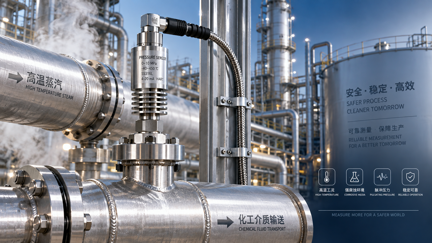
 Which parameters should be considered when selecting pressure sensors for high-temperature, corrosive, and pulsating operating conditions?
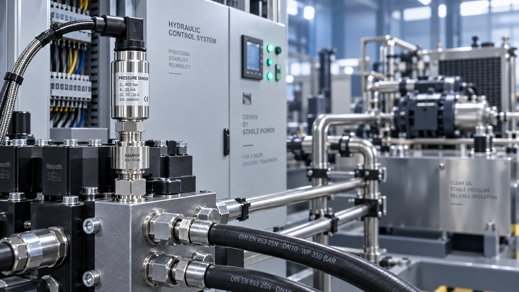
 Hydraulic equipment pressure fluctuates frequently. How can sensors be configured to improve control stability?