


News Center
—— NEWS CENTER ——
Xi'an Shenghongchuang Instrument Co., Ltd.
Contact: Mr. Zhang
Mobile: 15529283736
Email: shc-sensor@qq.com
Address: Fortune Building, Sanqiao Street, Xixian New Area, Xi'an, Shaanxi Province
Where Condensation Errors Arise in Steam Differential Pressure Flow Measurement
Relationship Between Differential Pressure Signals and Steam Flow
When steam pipeline flow is measured using a restriction device such as an orifice plate, nozzle, or Venturi tube, a Yokogawa differential pressure transmitter collects the pressure difference upstream and downstream of the restriction element, and the flow totalization system converts it into flow according to the square-root relationship. Although the differential pressure value is small, its stability directly affects steam metering results. Therefore, pressure tapping, impulse piping, and transmitter installation must be designed as a complete measurement system.
For saturated steam and superheated steam, the process medium temperature is usually significantly higher than the transmitter's allowable direct-contact temperature. In engineering practice, condensate pots, impulse pipes, and condensate columns are generally used to isolate high-temperature steam, allowing pressure to be reliably transmitted to the differential pressure sensor while preventing the diaphragm from prolonged high-temperature exposure.
Under ideal conditions, the condensate density, liquid-column height, and temperature in the high- and low-pressure impulse lines should be as consistent as possible. In this case, the additional pressure generated by the static liquid columns on both sides can offset each other, so the value read by the Yokogawa differential pressure transmitter mainly reflects the actual differential pressure generated by the restriction device.
Typical Deviations Caused by Unbalanced Condensate Columns
If the condensate pots on both sides are installed at different elevations, or the liquid levels in the impulse lines remain inconsistent for an extended period, the static pressure of the liquid columns will be superimposed on the actual differential pressure. For low-differential-pressure steam flow measurement, even a liquid-column height difference of only 100 mm may create an additional differential pressure of approximately 0.98 kPa, sufficient to cause a noticeable flow reading that is too high or too low.
Inconsistent condensate temperatures must also not be overlooked. When one impulse line is close to a high-temperature pipeline while the other is exposed to a low-temperature environment, differences in condensate density will occur, disrupting the static pressure compensation condition. Zero drift is often more apparent in outdoor installations in regions with large seasonal or day-night temperature variations.
In addition, residual gas, accumulated impurities, localized vaporization in impulse lines, and internal leakage of drain valves may all distort pressure transmission. If flow readings fluctuate in the field, the zero point fails to return after steam shutdown, or accumulated flow continuously deviates under the same load, the condensate system should be checked first rather than immediately concluding that the transmitter has failed.
Operating Conditions Requiring Particular Attention
Low-flow ranges, high-static-pressure conditions, and intermittent steam supply systems are particularly sensitive to changes in the condensate column. For example, at measurement points with an upper range limit of only 6 kPa to 10 kPa, an additional error at the 1 kPa level will be further amplified by square-root calculation, often exceeding the intuitive judgment of on-site personnel.
In steam branches subject to frequent start-ups and shutdowns, condensate in the impulse lines may be pushed by steam, causing repeated liquid-level migration. Without standardized commissioning procedures and regular liquid replenishment measures, even a highly accurate differential pressure transmitter will be difficult to maintain stable metering over the long term.
In areas with insufficient heat tracing or ambient temperatures below 0°C, impulse-line freezing and blockage should also be prevented. After freezing blockage occurs, pressure cannot be transmitted normally. In minor cases, flow indication becomes delayed; in severe cases, abnormal differential pressure may occur because pressure on one side is trapped, creating risks for both production control and energy accounting.
Key Control Points for Proper Installation of Yokogawa Differential Pressure Transmitters
Principles for Pressure-Tapping Locations and Condensate Pot Arrangement
For measurement on horizontal steam pipelines, pressure taps should generally be arranged near the sides of the pipe to reduce the impact of condensate and impurities on the taps. The specific pressure-tapping orientation, straight-pipe lengths upstream and downstream of the restriction element, and installation dimensions should be determined according to the restriction device used, design pressure, and relevant specifications, rather than adjusted arbitrarily based solely on experience.
The high- and low-pressure condensate pots should have the same specifications and volume and be installed at the same horizontal elevation. The centerline height difference between the two condensate pots should be kept within a small tolerance range; during engineering implementation, the elevation difference should preferably be controlled within 5 mm to reduce inherent zero error caused by liquid-column imbalance.
The connecting pipes from the pressure taps to the condensate pots should be as symmetrical as possible, avoiding one side being excessively long and the other too short, or one side being close to a heat source while the other has no insulation. A symmetrical arrangement not only helps ensure consistent condensation conditions on both sides, but also facilitates subsequent draining, liquid replenishment, and troubleshooting.
Impulse Pipe Slope, Insulation, and Freeze Protection
The impulse pipes from the condensate pots to the differential pressure transmitter should maintain a continuous, gentle downward slope so that condensate can stably fill the piping and avoid high points where gas can accumulate. The piping should not have repeatedly rising and falling “pocket” configurations; otherwise, air or flash vapor can easily become trapped, resulting in slow pressure transmission or even instantaneous fluctuations.
Outdoor steam measurement points should be equipped with insulation or heat tracing according to ambient temperature, steam shutdown duration, and medium parameters. The purpose of insulation is not simply to raise temperature, but to keep the thermal environments of the high- and low-pressure impulse lines similar. Excessive heat-tracing temperature may also re-vaporize localized condensate, thereby disrupting the stable liquid column.
The material, wall thickness, and fitting sealing method of impulse pipes should meet the requirements for maximum working pressure and steam temperature. After installation, leak-tightness and continuity checks should be performed. If leakage, flattening, excessively small bend radius, or incorrect valve manifold orientation is found, it should be rectified before commissioning to avoid hidden metering deviations during operation.
Commissioning, Elevation Compensation, and Zero Verification Should Be Managed Together
Establish Standardized Commissioning Procedures
For newly installed or overhauled steam differential pressure measurement systems, first confirm that the condensate pots and impulse lines have been filled with condensate as required, then slowly open the primary valves and impulse valves. During start-up, prevent high-temperature steam from directly rushing into the instrument side at high velocity, thereby avoiding disruption of the liquid columns and unnecessary single-side overpressure on the differential pressure sensor.
When using a three-valve manifold or five-valve manifold, equalizing, pressure introduction, and shutoff operations should be performed according to the on-site SOP. Zero verification should be conducted after pressure on both sides is fully balanced and the liquid filling of the impulse system has stabilized, rather than immediately after steam start-up, completion of draining, or before condensate-pot liquid levels have stabilized.
If there is a fixed elevation difference between the installation height of the differential pressure transmitter and the restriction-element pressure taps, the engineering design should calculate the liquid-column elevation compensation and handle it correctly in the range setting. Elevation compensation is static-pressure compensation caused by the installation configuration and is not equivalent to arbitrarily changing the zero point; confusing the two can easily conceal actual impulse-system problems.
Zero Verification Cannot Replace System Maintenance
When zero drift is found on site, it is not recommended to repeatedly modify the zero point of the Yokogawa differential pressure transmitter directly using a handheld communicator. If the deviation results from condensate imbalance, simple zero adjustment can only temporarily correct the reading at a particular moment. Once the liquid level changes again, the error will still occur and may make subsequent diagnosis more difficult.
The correct sequence is to first check the status of pressure-tapping valves, condensate-pot liquid levels, impulse-line continuity, and thermal conditions on both sides, and then perform equalization verification. Only after confirming that process conditions and impulse conditions are normal should zero verification, range review, or accuracy calibration be performed in accordance with metering procedures and instrument manuals.
For steam trade settlement, boiler energy-efficiency assessment, and important energy management points, records of each maintenance activity, draining, liquid replenishment, zero check, and parameter adjustment should be retained. Historical trend comparisons can help identify seasonal drift, valve manifold aging, and condensate system abnormalities earlier, reducing unexpected metering disputes.
Routine Maintenance Keeps Measurement Accuracy Within a Controllable Range
Establish Tiered Inspection Intervals
Routine steam measurement points can undergo monthly visual inspections in conjunction with plant operating procedures, focusing on damaged insulation, fitting leakage, loose supports, and heat-tracing abnormalities. For high-pressure steam, low-differential-pressure ranges, or loops responsible for energy accounting, key items are recommended to be included in more frequent inspection plans.
Every 3 to 6 months, the impulse system can be inspected according to on-site operating conditions to confirm whether condensate-pot liquid levels are symmetrical, drain valves are leak-tight, and valve manifold switching is flexible. The specific interval should be determined jointly by medium cleanliness, start-stop frequency, ambient temperature, and the company's metering management requirements.
During annual verification or calibration, attention should not be limited to the output accuracy of the differential pressure transmitter itself. Range, damping, elevation compensation, square-root extraction location, and associated temperature and pressure compensation parameters should also be reviewed. For systems using DCS or flow computers for totalization, parameters at the instrument end and the host system end must remain consistent.
Reducing Future Error Risks from the Selection Stage
Differential pressure transmitter selection should comprehensively consider steam design pressure, normal flow, minimum flow, differential pressure range, ambient temperature, and installation method. An excessively large range will reduce low-flow resolution, while an excessively small range may be exceeded during sudden load increases. A reasonable margin should generally be reserved based on the calculated actual differential pressure rather than estimating solely from pipe diameter.
Yokogawa differential pressure transmitters require coordinated design with condensate pots, valve manifolds, impulse pipes, and restriction devices. Details including flange standards, pressure ratings, wetted materials, process connection types, and protection ratings will all affect on-site installation quality and long-term maintenance costs.
Xi'an Shenghongchuang Instrumentation Co., Ltd. can provide technical support for differential pressure transmitters, matching valve manifolds, and industrial measurement and control solutions based on steam network parameters, restriction-element type, installation space, and control requirements. Before project implementation, on-site operating conditions should be verified and installation drawings confirmed to ensure that condensate error control is implemented throughout design, construction, commissioning, and maintenance.
Related Recommendations
![]() Southchip Technology Launches Its First Optical Sensor, the SC52115, for Wearable Devices
 How does a pressure sensor convert changes in applied force into usable electrical signals?
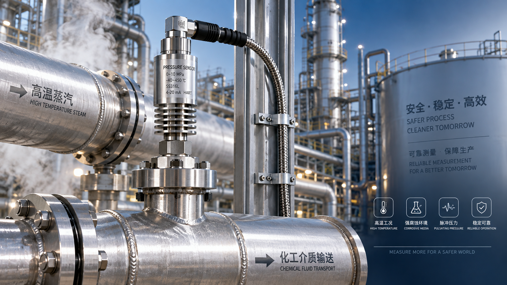
 Which parameters should be considered when selecting pressure sensors for high-temperature, corrosive, and pulsating operating conditions?
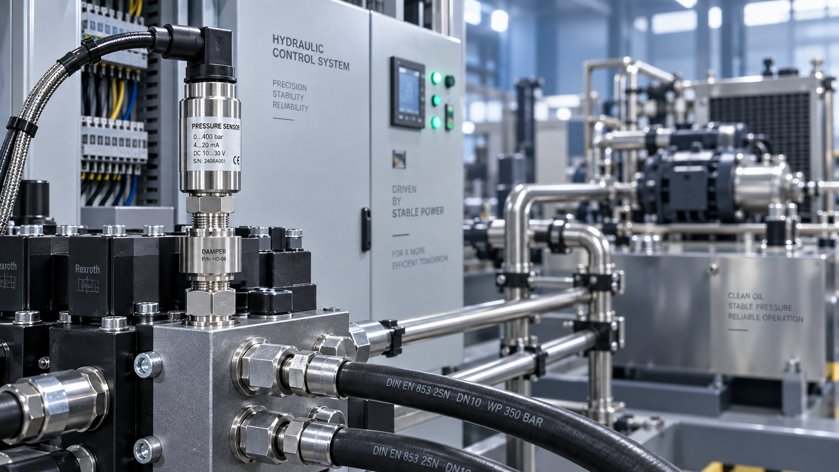
 Hydraulic equipment pressure fluctuates frequently. How can sensors be configured to improve control stability?