


News Center
—— NEWS CENTER ——
Xi'an Shenghongchuang Instrument Co., Ltd.
Contact: Mr. Zhang
Mobile: 15529283736
Email: shc-sensor@qq.com
Address: Fortune Building, Sanqiao Street, Xixian New Area, Xi'an, Shaanxi Province
When Selecting a HUBA Differential Pressure Transmitter for HVAC Systems, First Clarify the Measurement Task
In air handling units, fresh air units, cleanrooms, air ducts, filter sections, and water systems, differential pressure is not a single indicator. A HUBA differential pressure transmitter may be used to monitor supply and return air pressure differential, filter resistance, pressure differential across a fan, room pressure differential, or for circulating pump differential pressure control. Before selection, technical personnel should first define the measured object, pressure direction, normal operating value, and allowable alarm range.
Differential pressure in HVAC air systems is usually low. For example, the common pressure differential across a standard air-conditioning filter section ranges from 50Pa to 300Pa, while the final resistance of high-efficiency filters may reach 500Pa to 1000Pa; clean area differential pressure control commonly falls between 5Pa and 30Pa. If the measuring range is too large, small differential pressure changes are difficult to identify; if the range is too small, fan start-stop operations and damper actions may cause overpressure.
In water systems, differential pressure transmitters are more commonly used for variable-frequency pump control and hydraulic balance assessment. The design differential pressure of chilled water, cooling water, or heating water circuits is generally expressed in kPa. Static pressure, operating temperature, water quality, and the height difference between the pressure tapping points on both sides should also be verified to avoid mistaking pipeline network static pressure for the required differential pressure range.
For suppliers such as Xi'an Shenghongchuang Instrumentation Co., Ltd., which provides sensors, transmitters, and supporting control instruments, accurately collecting on-site parameters can improve product matching and facilitate subsequent non-standard configurations of range, interfaces, outputs, displays, and alarm functions, reducing the risk of repeated commissioning after installation.
Key Parameter 1: Measuring Range, Overload Capacity, and Measurement Accuracy
The Range Should Cover Normal Values While Allowing Margin for Operating Fluctuations
When selecting a HUBA differential pressure transmitter, the range should not simply be scaled up in proportion to the maximum design value. For filter differential pressure monitoring, the full-scale range can be set at 1.5 to 2 times the upper limit of normal differential pressure. For example, if the expected final resistance of a filter is 500Pa, a range of 0Pa to 1000Pa can be evaluated as a priority. This maintains resolution while accommodating short-term pressure fluctuations.
Cleanroom differential pressure control has higher requirements for low-range performance. If the target differential pressure is 10Pa to 15Pa, low differential pressure specifications such as 0Pa to 50Pa or 0Pa to 100Pa should generally be considered, with particular attention to zero-point stability and long-term drift. Using a 0Pa to 1000Pa product to monitor a 10Pa differential pressure may fail to meet stable control requirements even if the device can display the value.
It is also necessary to distinguish between the measuring range and single-side pressure resistance, dual-side pressure resistance, or overload capacity. Although air duct systems operate at low pressure, abnormal shocks may still occur during installation, purging, or incorrect piping connections; both sides of a water system have relatively high static pressure, and the transmitter must reliably measure small differential pressures within the allowable static pressure range.
Engineering documentation should clearly specify the three items of “measuring range, allowable overload, and maximum static pressure,” rather than merely stating “differential pressure sensor.” These three parameters together determine whether the device can measure accurately and withstand abnormal system conditions during actual operation.
Accuracy, Repeatability, and Stability Should Be Assessed in Relation to the Control Objective
For accuracy, it is important to determine whether it is expressed as a percentage of full scale, a percentage of reading, or total error. For 0Pa to 50Pa cleanroom differential pressure control, even a nominal accuracy of 1% of full scale may correspond to an error close to 0.5Pa; near a 10Pa control point, this error directly affects room differential pressure assessment. Therefore, actual performance in the low-range section should be considered.
For filter differential pressure monitoring, the focus is generally on trends and alarms, and extremely high accuracy may not be necessary, but stable output and good repeatability are required. If sensor signals fluctuate repeatedly, the controller may trigger alarms frequently, making it difficult for operation and maintenance personnel to determine whether the filter is actually clogged and increasing on-site troubleshooting workload.
Zero drift, temperature drift, and response time should also be confirmed. Changes in equipment room temperature, seasonal transitions between summer and winter, and variable-frequency fan speed control can all affect pressure conditions. In closed-loop control applications, excessive response time causes adjustment lag; for alarm-only applications, filtering or delay of 5 seconds to 30 seconds can be configured through the control system to reduce the impact of transient fluctuations.
During acceptance, it is recommended to compare the zero point and multiple points after the system is operating stably, covering at least the low point, common operating point, and high point. Archiving on-site measured data, alarm setpoints, and calibration records together helps with subsequent assessment of sensor drift, pipeline blockage, or air system performance degradation.
Key Parameter 2: Medium, Materials, and Installation Interfaces
The Medium Compatibility Logic Differs Between Air and Water Systems
HVAC supply and exhaust air systems generally handle clean air or air containing small amounts of dust. Particular attention should be paid to preventing condensate, oil mist, and corrosive gases from entering the pressure chamber. For kitchen exhaust, laboratory exhaust, underground garage exhaust, and similar locations, the resistance of the diaphragm, housing, and sealing materials should be verified according to the medium composition; products should not be selected solely based on ordinary air-conditioning operating conditions.
When a differential pressure transmitter comes into contact with the medium in chilled water and heating water systems, stainless steel material, sealing material, medium temperature, and additives should be verified. Ethylene glycol solutions, antifreeze, water treatment chemicals, or circulating water with high impurity content may all affect long-term sealing performance and measurement stability.
For air differential pressure measurement, pressure sensing tubes should be as short as possible, routed consistently, and arranged to avoid obvious water traps. Excessive differences in the lengths of the two pipelines, pipeline air leakage, or loose connections can cause low readings, slow response, or even incorrect positive and negative pressure direction. Rain protection and anti-condensation measures should be added in outdoor or high-humidity environments.
When installing in water systems, isolation valves should be installed at pressure tapping points on both sides. Air venting, blowdown, and a three-valve manifold should be configured where necessary to facilitate commissioning, calibration, and maintenance. For circulating water containing particulates, rational arrangement of pressure tapping locations is more important than simply upgrading the sensor rating, preventing impurities from accumulating in the pressure sensing passages.
Interfaces and Protection Rating Should Be Confirmed Together with Site Installation Conditions
The quantity, specifications, and connection methods of pressure interfaces should be confirmed. Air pressure products commonly use hose connections, requiring verification of the hose inner diameter and fixing method; water pressure products commonly involve threaded interfaces, flanges, or integrated valve manifolds. Interface mismatches increase the number of adapters, and more connection points mean higher risks of leakage and maintenance.
The protection rating should correspond to the installation location. Installation inside an indoor control cabinet can be considered according to electrical cabinet conditions; installation in fan rooms, rooftop equipment rooms, near condensate, or inside outdoor enclosures requires attention to dust resistance, moisture resistance, and vibration resistance. For humid locations, protection solutions rated IP65 and above are generally more beneficial for long-term operation.
Installation orientation should not be overlooked. Some low differential pressure products are affected at the zero point by vertical or horizontal installation. They should be fixed on site according to the instructions, and a zero-point check should be performed after pressure sensing tube connections are completed and when the fan is stopped or both sides are at equal pressure. Failure to perform zero calibration after installation may introduce an error from the beginning of low differential pressure measurement.
If the equipment is located near a highly vibrating fan foundation, a structurally reliable mounting bracket should be selected to prevent the sensor from directly bearing continuous vibration. Signal cables should be routed separately from power cables, and the shield should be grounded at one end to reduce electromagnetic interference from variable-frequency drives and motors.
Key Parameter 3: Output Signal, Power Supply, and Control System Integration
Determine the Signal Type According to the Input Capability of the BAS, DDC, or PLC
Common analog outputs in HVAC control include 4mA to 20mA, 0V to 10V, and 0V to 5V. If the transmission distance is long and on-site interference is significant, 4mA to 20mA generally provides better interference resistance and can assist in identifying open-circuit faults through abnormal current below 4mA; for short-distance connection to a DDC, 0V to 10V is also commonly used.
The signal range must be consistent with the engineering unit settings of the controller. For example, if a transmitter corresponds to 0Pa to 1000Pa, 4mA represents 0Pa and 20mA represents 1000Pa; if the DDC side is incorrectly set to 0Pa to 500Pa, the system display value will be doubled, and both filter alarms and fan control logic will be distorted.
The power supply method should be verified for 24VDC, 24VAC, or other requirements, along with control cabinet power capacity and common-ground arrangement. When multiple sensors share a power supply, the total load should be calculated with sufficient margin reserved; under long-distance wiring conditions, cable voltage drop should also be considered to ensure it does not affect normal device operation.
For equipment requiring local inspection, differential pressure transmitters with a digital display or button-setting function can be selected; for centralized monitoring projects, signal consistency, address management, and wiring maintainability should be prioritized. The display function should serve on-site maintenance rather than replace trend recording and alarm management by the control system.
Establish a Complete Verification Process from Selection to Maintenance
An Actionable Operating Condition Parameter Sheet Should Be Provided Before Ordering
During procurement or technical communication, it is recommended to provide the medium name, measuring range, maximum static pressure, operating temperature, accuracy requirements, output signal, supply voltage, interface type, protection rating, and installation location at one time. For air systems, whether the measurement concerns filters, fans, or room differential pressure should also be specified; for water systems, pipe diameter, medium composition, and control object should be supplemented.
Alarm values should not be based entirely on empirical values. Filters should be set according to initial resistance, rated airflow, and the manufacturer’s recommended final resistance; cleanrooms should be determined based on room classification, door gap leakage, and differential pressure relationships with adjacent areas; water systems should be adjusted based on the terminal differential pressure of the most unfavorable loop, combined with pump group control strategies.
After commissioning, pressure curves should be observed under different airflow rates, valve positions, and seasons. If values suddenly jump, priority should be given to checking for detached pressure sensing tubes, condensate accumulation, loose wiring, and controller range settings; if values rise slowly, the filter condition, airflow changes, or pipeline resistance changes should be evaluated comprehensively.
Xi'an Shenghongchuang Instrumentation Co., Ltd. can provide differential pressure transmitter parameter confirmation, product matching, and recommendations for supporting instruments based on the actual measurement object, control system, and installation environment of HVAC projects. Before determining the model, project technical personnel may submit on-site information on range, medium, static pressure, output, and interfaces to develop a selection solution that better meets operating requirements.
Related Recommendations
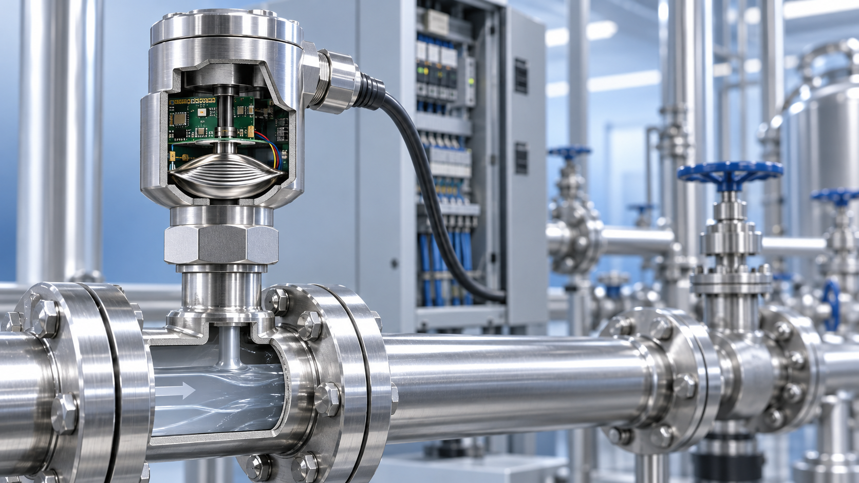
 How does a pressure sensor convert changes in applied force into usable electrical signals?
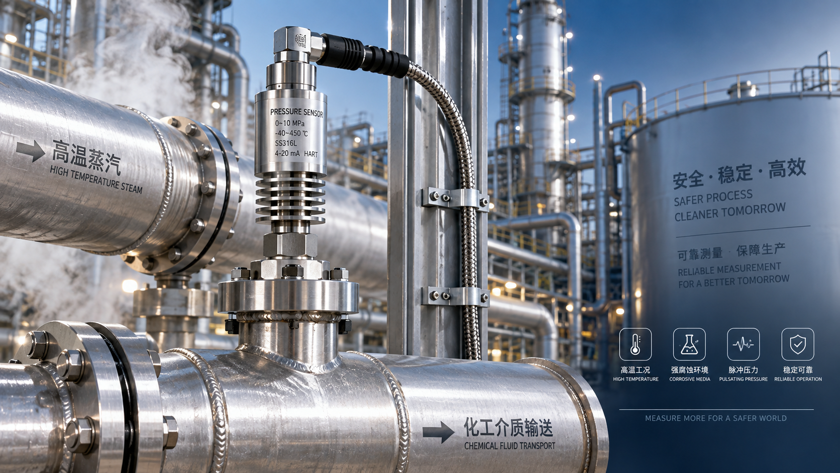
 Which parameters should be considered when selecting pressure sensors for high-temperature, corrosive, and pulsating operating conditions?
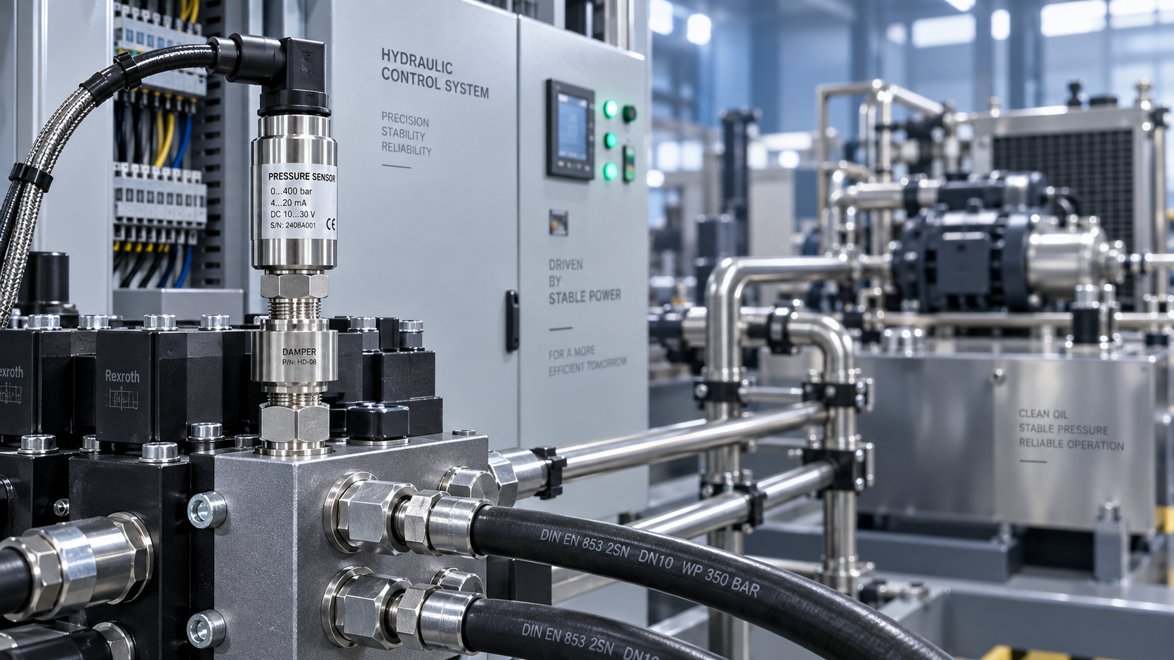
 Hydraulic equipment pressure fluctuates frequently. How can sensors be configured to improve control stability?
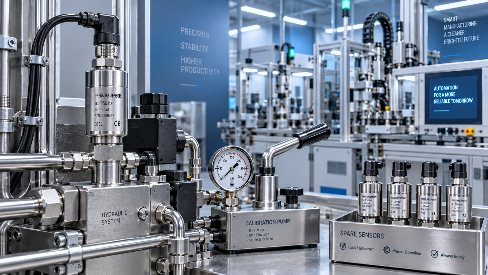
 When purchasing pressure sensors, how can you evaluate service life and total maintenance costs beyond the unit price?