


News Center
—— NEWS CENTER ——
Xi'an Shenghongchuang Instrument Co., Ltd.
Contact: Mr. Zhang
Mobile: 15529283736
Email: shc-sensor@qq.com
Address: Fortune Building, Sanqiao Street, Xixian New Area, Xi'an, Shaanxi Province
Why Sensor Selection Matters for Cleanroom Differential Pressure Monitoring
Cleanroom differential pressure is used to maintain directed airflow and prevent particles, microorganisms, or odors from lower-grade areas from flowing back into higher-grade areas. Scenarios such as aseptic pharmaceutical production, hospital operating departments, electronic semiconductor facilities, food filling, and laboratories typically require continuous monitoring of pressure differences between rooms and corridors, buffer rooms and core areas, as well as supply-air and return-air sections.
Taking adjacent clean areas as an example, common design differential pressures are generally around 5 Pa, 10 Pa, 15 Pa, 20 Pa, or 30 Pa. A larger differential pressure value is not necessarily better; it must remain stable in the designed direction under conditions such as door opening, fan start-up and shutdown, changes in filter resistance, and personnel movement. Therefore, the sensor's low-range measurement capability, zero stability, and response speed directly affect environmental control performance.
WIKA differential pressure transmitters can be used to detect cleanroom positive pressure, negative pressure, and local differential pressure, but the specific model cannot be determined solely by the term “differential pressure transmitter.” Project managers should assess its suitability in terms of range, accuracy, installation location, display requirements, signal output, and alarm interlock method, and then finalize the model based on on-site verification results.
Xi'an Shenghongchuang Instrumentation Co., Ltd. can provide differential pressure transmitters, intelligent digital display control instruments, and supporting control solutions for clean air-conditioning systems, duct static pressure, room differential pressure, and other requirements. For retrofit projects, the input type, power supply method, and communication interface of the existing controller should first be verified to avoid signal incompatibility after equipment replacement.
Which Cleanroom Differential Pressures Are Suitable for Monitoring with WIKA Differential Pressure Transmitters
Differential Pressure Between Adjacent Rooms and Corridors
This is the most common monitoring location in cleanrooms, mainly used to confirm whether a clean area maintains positive pressure relative to a non-clean area, or whether isolation and contamination-control areas maintain negative pressure. For room differential pressures with a design target of 10 Pa to 30 Pa, a low differential pressure range product that covers the operating point and provides sufficient resolution should be selected.
In pharmaceutical clean plants, differential pressure can be monitored between changing areas, buffer zones, clean corridors, filling rooms, and auxiliary rooms; in hospital environments, it can be used to monitor pressure relationships between general wards and buffer zones, areas adjacent to operating departments, and isolation wards and corridors. For negative-pressure isolation applications, the tubing directions of the high-pressure and low-pressure ports must be clearly identified to prevent reversed displayed values or control logic.
When doors are opened and closed frequently, instantaneous differential pressure fluctuations do not necessarily mean that the system has failed. The transmitter and control system should set a reasonable alarm delay according to the actual process, such as 5 seconds, 10 seconds, or 30 seconds, to reduce false alarms caused by momentary door opening without masking persistent imbalance in the supply and exhaust air systems.
Applicable Scenario Comparison
For areas requiring on-site inspections, a configuration with a digital display can be selected so that duty personnel can directly read the current differential pressure. For centralized control projects, signals such as 4 mA to 20 mA, 0 V to 10 V, or RS485 can be connected to DDC, PLC, or building automation systems to enable trend recording and centralized alarms.
How to Match Low Differential Pressure Range and Accuracy
The Range Should Not Be Enlarged Blindly
Cleanroom differential pressure is generally a very low differential pressure measurement. If the on-site design differential pressure is 15 Pa but a large-range product of 0 Pa to 1000 Pa is selected, it will not exceed the range, but the effective resolution and relative measurement accuracy may fail to meet control requirements. Normally, the operating differential pressure should fall within 30% to 80% of the range to balance resolution and fluctuation margin.
For example, for rooms with a target differential pressure of 10 Pa to 20 Pa, ranges of 0 Pa to 50 Pa, 0 Pa to 100 Pa, or bidirectional low ranges may be prioritized for evaluation. For areas with a target differential pressure of 30 Pa to 50 Pa, a range of 0 Pa to 100 Pa or a more suitable range can be selected according to door-opening fluctuations and airflow adjustment range. The final selection should be based on the actual technical specifications, calibration capability, and project acceptance standards of the equipment.
Accuracy should be assessed in combination with full-scale error, long-term stability, and zero drift. For low cleanroom differential pressure, simply comparing percentage accuracy is not meaningful; it must also be converted into actual Pa values. If the full scale is 100 Pa and the accuracy is 1% FS, the theoretical error is approximately 1 Pa; near a 10 Pa control point, 1 Pa may already have a significant impact on alarm threshold determination.
Common Selection Reference
Whether a WIKA differential pressure transmitter is suitable for a specific cleanroom depends on whether its particular model can cover the required low differential pressure range and meet project requirements for accuracy, repeatability, temperature drift, and long-term operational stability. A complete data sheet should be obtained before purchase to confirm the nominal range, allowable overpressure, output error, and ambient temperature range.
Installation Method and System Interlock Determine Monitoring Reliability
Pressure Sampling Tubing Should Be Short, Straight, and Sealed
Room differential pressure transmitters are typically connected to two spaces through two pressure sampling tubes. The high-pressure and low-pressure ports should be connected according to the design drawings, and the tubing should be kept as short as possible to avoid flattening, blockage, and excessive bending. If the pressure sampling tubing leaks, even a highly accurate sensor will produce low readings, increased fluctuations, or unstable zero return.
The sensor installation location should avoid supply-air outlets, return-air outlets, door gaps, areas subject to frequent personnel impact, and strong electromagnetic interference sources. When installed on a wall, consideration should be given to whether maintenance personnel can conveniently view the display, inspect tubing connections, and perform zero calibration. In locations with suspended ceilings or interstitial spaces, the pressure sampling port location should reflect the actual room static pressure rather than local airflow impact pressure.
If the transmitter is connected to a control system, in addition to confirming 24 VDC or other power supply conditions, the analog input range must also be verified. For example, when 4 mA to 20 mA corresponds to 0 Pa to 50 Pa, the control system's engineering range, high alarm limit, low alarm limit, and open-circuit detection should be configured accordingly. Inconsistent parameter definitions will result in discrepancies between on-site displays and central control interface values.
Alarm and Control Recommendations
Cleanroom differential pressure alarms should establish upper and lower limits around the design differential pressure rather than directly copying parameters from other projects. For example, when the design value is 15 Pa, warning values, alarm values, and recovery values can be set according to process risk and validation requirements, with appropriate deadband retained to avoid repeated alarms when the value fluctuates near the threshold.
For critical areas, differential pressure signals can be interlocked with supply fans, exhaust fans, variable-frequency drives, audible and visual alarms, and host computer recording systems. When differential pressure remains below the allowable value, the system should be able to prompt management personnel to check access control status, damper opening, filter blockage, and supply-exhaust airflow balance, rather than merely retaining an isolated alarm indicator.
After installation is completed, zero confirmation, positive and negative port verification, analog signal verification, and door opening/closing disturbance testing are recommended. Commissioning records should include the measuring point name, design differential pressure, actual displayed value, output signal, alarm threshold, and test date, providing a basis for subsequent cleanroom validation, metrological calibration, and fault traceability.
Key Implementation Points for Selecting Differential Pressure Transmitters for Cleanroom Projects
Confirm the Configuration Starting with the Operating Condition List
Before selecting a WIKA differential pressure transmitter or another cleanroom differential pressure monitoring sensor, first prepare a list of measurement points: where the two pressure sampling ports are located, what the design differential pressure is, the normal fluctuation range, whether negative pressure is required, whether local display is needed, and whether data must be uploaded to a PLC, DDC, or building automation platform.
For new construction projects, sensor selection should proceed in parallel with HVAC design, cleanroom validation, and automation drawings. For existing workshop retrofits, first check whether the existing differential pressure truly reflects room conditions. In some older systems, abnormal differential pressure may result from aging pressure sampling tubes, loose fittings, dust accumulation in filters, or airflow imbalance, and direct sensor replacement may not necessarily be required.
When supplying products, suppliers should clearly specify the range, accuracy, output, power supply, installation dimensions, pneumatic connection interface, protection requirements, and calibration method. For areas with high humidity, corrosive gases, significant temperature fluctuations, or frequent cleaning and disinfection, enclosure material, environmental adaptability, and maintenance intervals should also be confirmed to avoid using standard configurations under unsuitable operating conditions.
Maintenance and Calibration Are Essential
Cleanroom differential pressure monitoring is not equipment that remains maintenance-free after a single installation. It is recommended to establish an inspection plan based on the company's quality system and frequency of use, regularly checking whether displayed values are stable, tubing connections are loose, pressure sampling ports are blocked, and access control and fan operating conditions have changed. Critical clean areas may be calibrated annually or at intervals specified by the project.
When differential pressure is found to remain low, troubleshooting should proceed in the order of “airflow balance, door and window sealing, filter resistance, damper status, pressure sampling tubing, and transmitter calibration.” This avoids determining faults based solely on a single reading and also helps reduce the costs of production shutdown maintenance and repeated equipment replacement.
Overall, WIKA differential pressure transmitters are suitable for cleanroom differential pressure monitoring projects with specific requirements for brand specifications, measurement stability, and system integration, particularly for measurement points such as room differential pressure, buffer zone differential pressure, negative-pressure isolation, and supply/return air static pressure. The final model should be verified based on actual operating conditions and technical documentation; a single brand name cannot replace complete model selection.
To determine a cleanroom differential pressure monitoring solution, provide Xi'an Shenghongchuang Instrumentation Co., Ltd. with the cleanliness class, measurement point locations, target differential pressure, signal type, and control system requirements. Technical personnel can then verify the range and installation conditions and configure differential pressure transmitters, digital display instruments, and alarm interlock solutions suitable for on-site use.
Related Recommendations
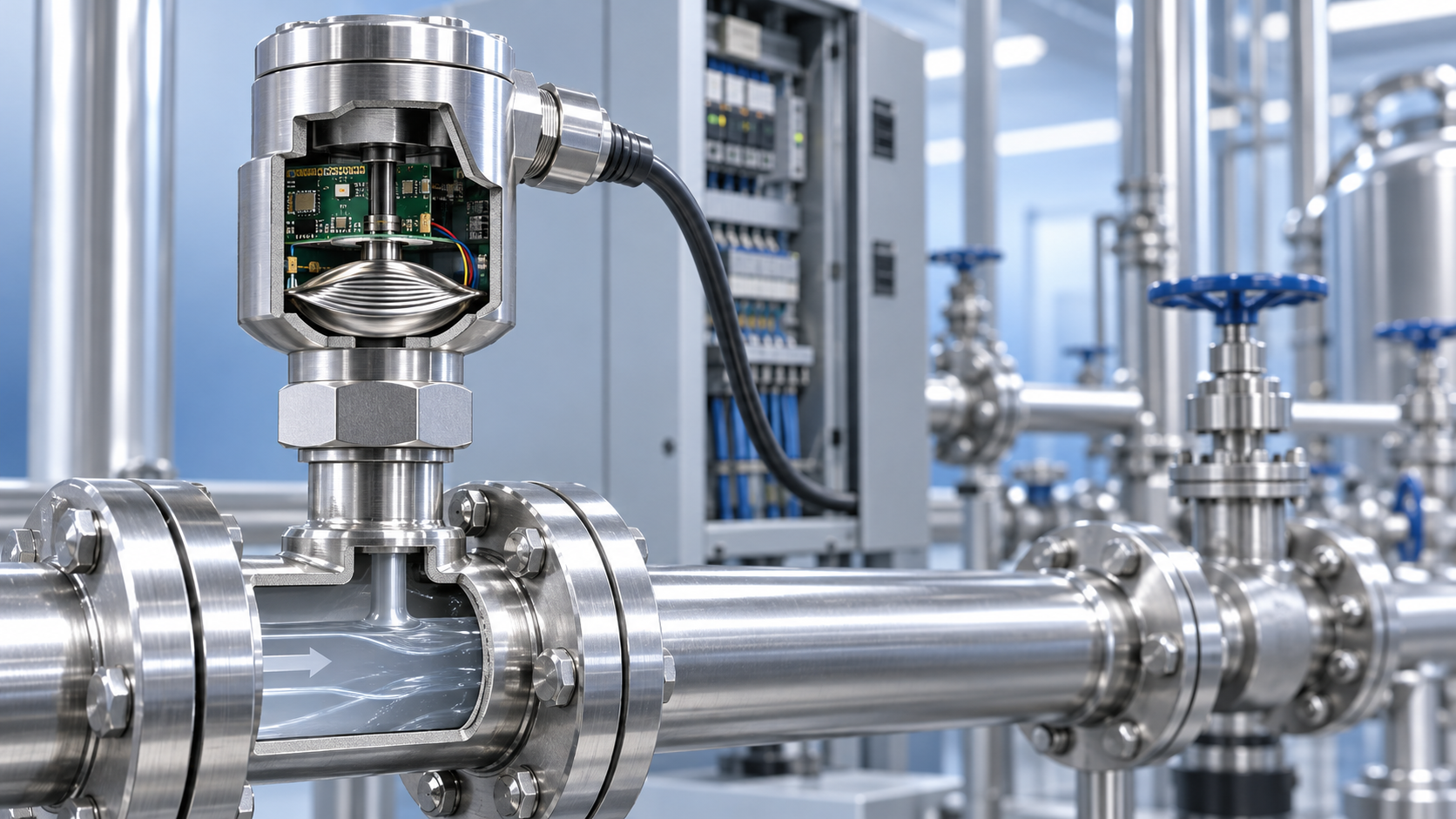
 How does a pressure sensor convert changes in applied force into usable electrical signals?
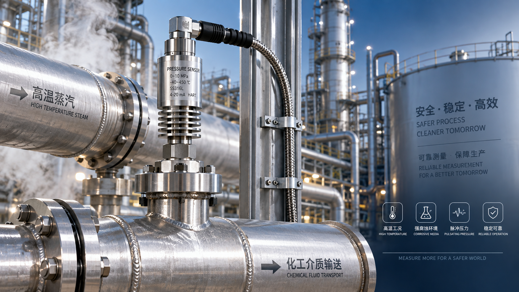
 Which parameters should be considered when selecting pressure sensors for high-temperature, corrosive, and pulsating operating conditions?
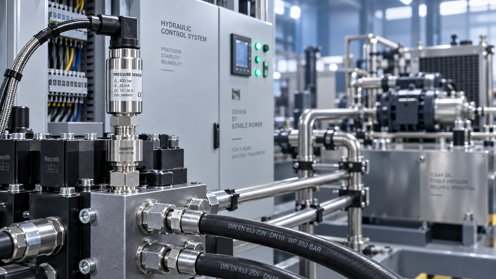
 Hydraulic equipment pressure fluctuates frequently. How can sensors be configured to improve control stability?
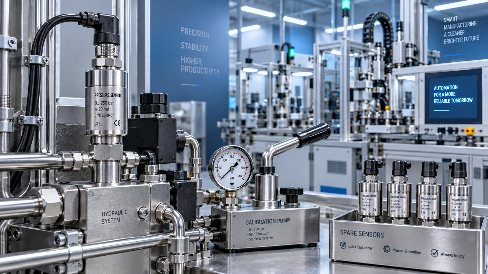
 When purchasing pressure sensors, how can you evaluate service life and total maintenance costs beyond the unit price?