News Center
—— NEWS CENTER ——
Xi'an Shenghongchuang Instrument Co., Ltd.
Contact: Mr. Zhang
Mobile: 15529283736
Email: shc-sensor@qq.com
Address: Fortune Building, Sanqiao Street, Xixian New Area, Xi'an, Shaanxi Province
How do you determine the cable length for a pressure transmitter with a direct cable lead? When purchasing, consider the installation distance, cable routing path, and operating conditions to avoid choosing a cable that is too short or leaving excessive excess length. In addition to measuring the distance at the installation site, check the output signal, power supply conditions, and wiring method to ensure the cable is long enough for installation without affecting the stable operation of the instrument.
I. Measure Along the Actual Cable Routing Path First
Measure from the Cable Outlet to the Terminal
Measure the cable length from the transmitter’s actual cable outlet, following the planned cable tray, conduit, or equipment wiring duct all the way to the terminals in the junction box or control cabinet. Do not measure only the straight-line distance between the two points, as this may overlook the extra length needed for bends, vertical runs, and routing around obstacles.
When measuring, include internal equipment wiring, cabinet cable entry, and the space needed to organize the wires in front of the terminal block. For sections that pass through walls, cross equipment, or run through protective conduit, calculate the length along the cable’s actual route to avoid tension at the cable outlet caused by underestimating the required length.
If construction has not yet begun on site, estimate the length from the layout drawing and confirm the cable tray elevation, junction box location, and cable entry direction with the installation team. For projects where equipment locations may change, clarify the range of possible changes before ordering, then determine the required allowance.
Allow a Reasonable Length for Installation and Maintenance
The extra length is primarily for terminating the cable, routing it around bends, and future maintenance. It should not be increased by simply applying a fixed multiplier. For equipment installed over a short distance, determine the allowance based on the space inside the cabinet. For longer routes or where the equipment location has not yet been finalized, add an appropriate allowance based on the actual uncertainty.
For example, if the measured route is 8 meters, and an estimated 1 meter is needed for cabinet wiring and organizing the cable at the transmitter end, with another 1 meter reserved for maintenance and minor position adjustments, a preliminary cable length of 10 meters may be specified. This is only a calculation example; the actual allowance should be determined by the installation space and maintenance requirements.
Avoid leaving excessive cable length without a clear reason. Any surplus cable must be secured properly to prevent water accumulation, crushing, or being bundled with power cables. For vented cables, also protect the vented end to prevent moisture and contaminants from entering.
II. Calculate Based on Signal and Power Supply Conditions
Considerations for Different Output Types
Whether a cable can meet transmission requirements depends not only on the distance, but also on the transmitter’s output type, supply voltage, receiving equipment input requirements, and cable characteristics. A 4–20 mA current signal is generally suitable for industrial transmission, but this does not mean the cable can be extended without limit.
For a two-wire current output, the cable’s round-trip resistance causes a voltage drop. Calculate the line voltage drop at the maximum operating current and expected temperature, and add the voltage drops from the receiver, isolator, and other equipment. Ensure that the voltage at the transmitter remains within the product’s permissible range.
For voltage outputs, consider line voltage drop, receiver input impedance, and the effect of interference on measurement results. For digital communications, also check the cable type, length, and termination configuration specified by the communication protocol. The product documentation and system calculations should be used to determine the permitted distance.
Use Loop Voltage Drop to Determine Whether the Cable Length Is Feasible
For a two-wire loop, estimate the cable voltage drop by multiplying the maximum operating current by the cable’s total round-trip resistance, then add the voltage drops from other loop loads. Use the cable resistance under actual operating conditions rather than calculating based on the one-way length alone.
Assuming a total round-trip cable resistance of 40Ω, at 20mA the cable voltage drop is approximately 0.8V. If a 24V DC power supply is used, also subtract the voltage drops from the receiver and other equipment, and allow for power supply fluctuations before determining whether the voltage at the transmitter is sufficient.
The 20mA calculation above is provided only as an illustrative example. Actual calculations should also account for the maximum operating current or fault indication current the equipment may reach, and should be based on the transmitter’s minimum operating voltage, receiver specifications, and manufacturer requirements.
III. Select the Cable and Wiring Method Based on Site Conditions
Confirm Protection Requirements in Addition to Cable Length
For a direct cable outlet design, the cable is usually sealed to the transmitter. Do not modify or dismantle the cable outlet at the installation site. When ordering, also specify whether the installation is indoors or outdoors, whether the cable will be exposed to oil, corrosive media, sunlight, or ambient temperature extremes, so the supplier can confirm the sheath material and protection method.
Near motors, variable-frequency drives, or high-power equipment, route signal cables separately from power cables whenever possible. If shielding is required, ground the shield according to the equipment and system design requirements. Where the cable passes sharp edges or sections subject to frequent movement, provide abrasion protection, secure the cable, or use a cable carrier as appropriate.
For gauge-pressure products, confirm whether a vented cable is used and check the installation requirements for the vented end. The junction box must meet site protection requirements, while the vent path must remain unobstructed as specified by the manufacturer. Do not block the vent structure arbitrarily to prevent water ingress.
Confirm the Splicing Method Before Extending the Cable
If the supplied cable is too short, first confirm with the supplier whether it can be extended and what type of cable and wiring method are permitted. After extension, recalculate the total line resistance and signal transmission conditions. Do not connect the wires based solely on matching wire colors.
Place the splice where it can be inspected and where it meets site protection requirements, using a junction box or connector suitable for the operating conditions. In outdoor, damp, or potentially corrosive environments, pay particular attention to sealing, grounding, and mechanical securing of the connection.
Extending a vented cable also requires maintaining continuity of the vent path and providing moisture protection. The supplier should provide a suitable solution. In hazardous areas requiring explosion protection, the cable, connectors, and installation method must all comply with the applicable explosion-proof certification and site regulations. Do not make unauthorized modifications.
IV. Confirm Key Parameters When Ordering
Specify the Cable Length Along with the Instrument Configuration
When requesting a quotation from the manufacturer, provide the measured medium, pressure type, range, process connection, output signal, supply voltage, and installation environment. For the cable, specify the total required length, whether a vented design is needed, the termination type, and any special sheath requirements.
If the process requires measuring the pressure difference between two points, select a suitable differential pressure transmitter rather than choosing a standard pressure transmitter based only on its cable configuration. For example, the domestic PY302 diffusion-silicon integrated differential pressure transmitter is used to measure differential pressure and offers a 4–20mA output, with accuracy options of 0.5, 0.25, and 0.1 class. Confirm the specific range, construction, and cable outlet type before ordering.
Xi’an Shenghongchuang Instrumentation Co., Ltd. can discuss product selection based on on-site measurement and control requirements. Before purchasing, compile the cable routing length, allowance, power supply parameters, and receiver specifications and submit them to the technical team. Confirm the cable specification and final order length before arranging production or installation.
Related Recommendations
 What Can Hydraulic Pressure Transmitters Measure? Applications from Reservoir Water Levels to Pipeline Pressure
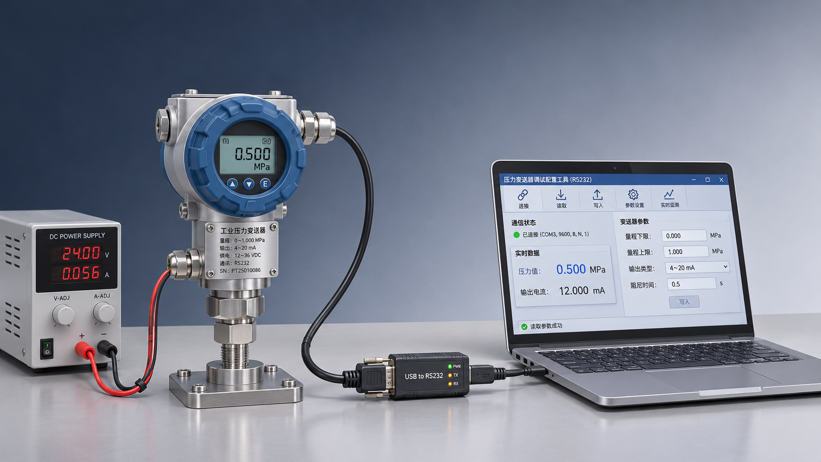
 Connecting an RS232 Pressure Transmitter to a Host Computer: Serial Port Parameters and Communication Troubleshooting
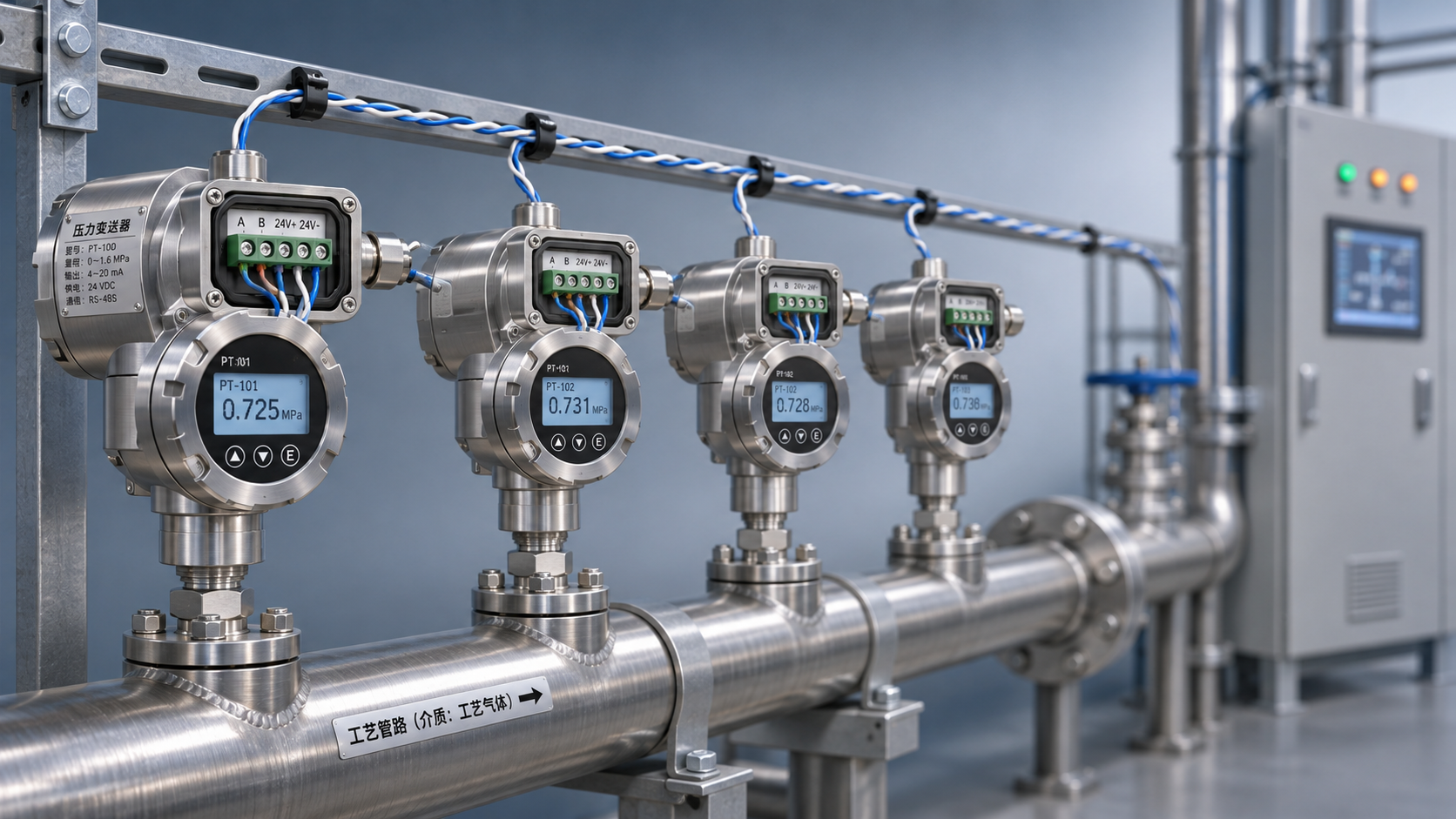
 RS485 Pressure Transmitter Multi-Drop Networking: How to Set the Terminating Resistor and Device Addresses?
 How Does a HART Pressure Transmitter Use an Overlay Signal for Remote Configuration?