News Center
—— NEWS CENTER ——
Xi'an Shenghongchuang Instrument Co., Ltd.
Contact: Mr. Zhang
Mobile: 15529283736
Email: shc-sensor@qq.com
Address: Fortune Building, Sanqiao Street, Xixian New Area, Xi'an, Shaanxi Province
Common Signs of Signal Attenuation in Remote Pressure Transmitters
Remote pressure transmitters typically transmit field pressure data to PLCs, DCSs, display instruments, or host computers via 4-20mA, 0-10V, RS485, or wireless communication. When signal attenuation occurs, the most apparent symptoms are persistently low readings at the control end, increased fluctuations, or a noticeable delay in data response following changes in field pressure.
Taking a 4-20mA two-wire pressure transmitter as an example, within the rated range, 4mA typically corresponds to the lower range limit, while 20mA corresponds to the upper range limit. If the actual pressure is stable at approximately 50% of the range, the theoretical output should be close to 12mA. If the control end receives only 10.8mA, this will result in a measurement deviation of approximately 7.5% of the range after conversion.
Signal attenuation does not necessarily mean that the transmitter itself is damaged. Insufficient supply voltage, excessive cable resistance, oxidized wiring terminals, improper shield grounding, strong electromagnetic interference, and incorrect input module parameter settings can all cause data distortion. During troubleshooting, first distinguish between an actual current drop and an abnormality in control-end acquisition.
Distinguishing Attenuation from Ordinary Zero Drift
Zero drift usually appears as a relatively fixed deviation across the entire range, such as a continuous reading that is 0.2MPa too high under no-load conditions. Signal attenuation, however, is often related to transmission distance, load impedance, equipment startup and shutdown, or changes in ambient humidity, and the severity of the abnormality may vary with operating conditions.
If a multimeter directly measures 12.00mA at the transmitter output terminal but only 11.35mA at the control cabinet input terminal, the wiring, terminals, and intermediate isolation equipment should be checked first. In a standard current loop, the current at series measurement points should normally be essentially the same, with no significant difference.
If the current at the field end and control end is consistent but the value displayed by the system differs substantially, check the PLC analog module range, engineering units, filtering time, and configuration formula. For example, if the module is set for 0-20mA input while the field device actually uses 4-20mA output, it will directly cause a scaling conversion error.
Why Power Supply and Wiring Issues Cause Signal Abnormalities
Insufficient Loop Power Margin
Two-wire remote pressure transmitters require power from the loop supply. The common supply range is 12VDC to 36VDC, while 24VDC is widely used in industrial applications. When cables are excessively long, loads are too high, or power supply capacity is insufficient, the actual voltage available at the transmitter may fall below the minimum operating voltage, resulting in limited output or intermittent disconnection.
For example, in a loop with a 24VDC supply and a 250Ω control-end input resistance, the input voltage drop is approximately 5V at full-scale 20mA. If the total wiring resistance reaches 400Ω, the wiring voltage drop is approximately 8V, leaving only about 11V at the transmitter, which is close to or even below the stable operating requirement of some products.
It is recommended to measure the supply terminal voltage of the transmitter under 20mA or near-full-range conditions, rather than measuring only the power supply output in the control cabinet. For projects with transmission distances exceeding 300 meters, high ambient temperatures, or multiple devices sharing one power supply, cable size, power supply capacity, and allowable load impedance should be calculated during the design stage.
Poor Cable and Terminal Contact
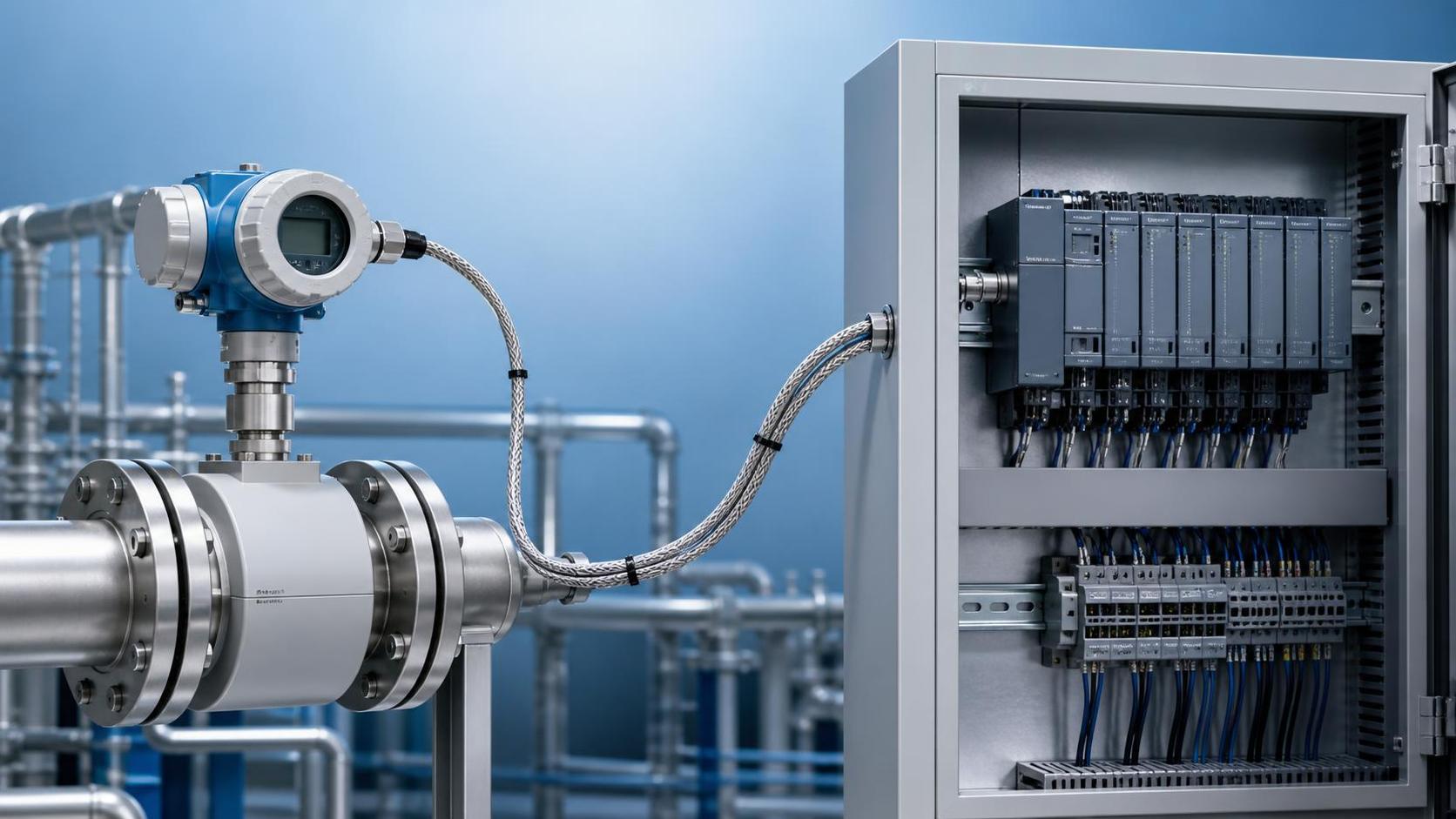
Cable trays, junction boxes, and instrument cabinets in industrial environments are susceptible to vibration, dust, condensate, and corrosive gases. If terminal screws are not tightened, conductor copper cores are oxidized, or cable jackets are damaged and allow water ingress, loop resistance will increase, and the signal may gradually decline, fluctuate randomly, or be momentarily interrupted during equipment operation.
In high-humidity areas, focus on checking the transmitter cable outlet, field junction box, and intermediate cable joints. Where protection is inadequate, moisture can enter the terminal chamber along the cable and create weak leakage paths, particularly affecting high-impedance voltage signals and RS485 communication signals.
Troubleshooting can be performed using a sectional isolation method: first disconnect the control cabinet wiring and measure insulation, then inspect intermediate junction boxes section by section, and finally compare the output after replacing the wiring with a temporary short cable. If the short-cable test returns to normal, the issue can usually be confirmed to be in the transmission path rather than inside the pressure transmitter.
Effects of Environmental Interference and Installation Methods
Signal Fluctuations Caused by Strong Electromagnetic Environments
Variable frequency drives, servo drives, high-power motors, welding equipment, and high-frequency switching power supplies generate strong electromagnetic interference in the surrounding area during operation. If the pressure transmitter signal cable is routed parallel to power cables with insufficient spacing, irregular fluctuations of 0.1mA to 0.5mA may occur at the control end.
The interference resistance of 4-20mA current signals is generally better than that of 0-10V voltage signals. Therefore, 4-20mA output is a more reliable choice for automated production lines with long transmission distances and significant field interference. For communication-type pressure transmitters, also check the RS485 termination resistor, communication address, and baud rate settings.
The shield layer should generally use single-end grounding, typically grounded reliably at the control cabinet side, to prevent ground loops caused by grounding at both ends. Signal cables and 380V power cables should be routed in separate cable trays. If separation cannot be avoided, install a metal partition or maintain sufficient spacing, and cross the cables at right angles whenever possible.
Installation Medium Conditions Also Require Verification
High-temperature steam, strongly pulsating hydraulic pressure, and media containing particles not only affect the service life of measuring elements but can also make the output signal appear to be “attenuated.” For example, when an impulse pipe becomes blocked, the actual pressure cannot be transmitted to the sensor in a timely manner, causing the control-end display to lag behind the actual process pressure.
When installed at pulsating locations such as pump outlets or compressor outlets, dampers, buffer tubes, or appropriate digital filtering parameters should be configured according to operating conditions. Too short a filtering time amplifies instantaneous pulses, whereas too long a filtering time may mask actual pressure changes. Settings should be balanced based on control response requirements.
For corrosive, easily crystallizing, or high-viscosity media, select compatible wetted materials, diaphragm structures, and process connection methods. Xi'an Shenghongchuang Instrumentation Co., Ltd. can provide targeted selection of pressure transmitters and supporting intelligent digital display control instruments based on range, medium temperature, installation space, and signal interface.
Troubleshooting Procedure for Remote Pressure Transmitter Signal Attenuation
Conduct Step-by-Step Testing from the Device End to the Control End
The first step is to confirm whether the actual process pressure is reasonable. This can be verified using a standard pressure gauge, portable pressure calibrator, or a backup measurement point. If both the field mechanical gauge and transmitter display are abnormal, first address process issues such as blocked pressure taps, valves not fully open, or medium pulsation.
The second step is to connect a suitably accurate multimeter in series at the transmitter output terminal and record the actual outputs near 4mA, 12mA, and 20mA. Then perform the same measurements at the control cabinet analog input terminal. If the difference between the two measurement points is obvious, inspect the wiring and intermediate equipment. If the values are consistent, proceed with module and software configuration checks.
The third step is to use a signal generator to input five calibration points of 4mA, 8mA, 12mA, 16mA, and 20mA to the control end. If the PLC or display instrument conversion result does not match the configured range, correct the input type, upper and lower range limits, engineering units, and alarm thresholds instead of blindly replacing the pressure transmitter.
Establish a Preventive Maintenance Mechanism
For critical pressure measurement points, it is recommended to inspect terminal tightness, cable appearance, and grounding continuity every 3 months. For high-temperature, high-humidity, or highly corrosive locations, inspections may be shortened to monthly intervals. Inspection records should include supply voltage, output current, field pressure, and the control-end displayed value to facilitate the identification of trending abnormalities.
The calibration interval for pressure transmitters should be determined according to operating conditions, accuracy class, and quality management requirements. In general industrial applications, comparative verification can be performed every 6 months to 12 months. For measurement points used for critical interlocks, metering, or safety monitoring, a stricter calibration plan should be implemented in accordance with company procedures.
When a remote pressure transmitter frequently experiences signal attenuation, zero drift, or unstable communication, organize information on the range, output method, power supply conditions, cable length, medium parameters, and field photographs for systematic diagnosis by professional technical personnel. Timely completion of selection review, wiring rectification, and calibration maintenance can effectively ensure the long-term stable operation of industrial measurement and control systems.
Related Recommendations
 How to Select an Industrial Flowmeter in Xi'an Based on Operating Conditions?
 What on-site measurements are Shaanxi portable flowmeters suitable for?
 What Costs Should Be Considered When Purchasing Small Flowmeters in Xi'an?
 How can Shaanxi remote-transmission flowmeters reduce signal transmission errors?