News Center
—— NEWS CENTER ——
Xi'an Shenghongchuang Instrument Co., Ltd.
Contact: Mr. Zhang
Mobile: 15529283736
Email: shc-sensor@qq.com
Address: Fortune Building, Sanqiao Street, Xixian New Area, Xi'an, Shaanxi Province
What to Do When a Local Display Pressure Transmitter Gives Inaccurate Readings
When a local display pressure transmitter shows inaccurate readings, value drift, display fluctuations, or obvious deviation from a standard pressure gauge, a product fault should not be determined based on a single reading alone. Pressure measurement results are affected by many factors, including installation location, pressure tapping conditions, power supply quality, wiring method, range matching, medium characteristics, and calibration status.
For 4–20mA pressure transmitters commonly used in industrial sites, an output current deviation of 0.16mA theoretically corresponds to a measurement shift of approximately 0.01MPa within a 0–1.0MPa range. If the range is expanded to 0–10MPa, the same current deviation corresponds to a pressure error of approximately 0.1MPa. Therefore, before troubleshooting, confirm the complete transmitter model, actual range, output signal, and accuracy class.
Xi'an Shenghongchuang Instruments & Meters Co., Ltd. recommends that on-site maintenance personnel follow the sequence of “confirming the phenomenon, checking installation, verifying electrical connections, validating the range, investigating the medium, and performing calibration.” This helps avoid repeated disassembly and installation, while more quickly distinguishing between system errors, operating condition changes, and abnormalities in the pressure transmitter itself.
First Confirm the Type of Reading Deviation
Difference Between Zero Drift and Full-Scale Deviation
Zero drift is typically indicated when the local display pressure transmitter cannot return to 0 after the equipment is depressurized, or still displays a positive or negative value when connected to the atmosphere. For gauge pressure products, the reading should be close to zero after normal pressure release; the allowable error should be assessed according to the product accuracy class. For example, for a Class 0.5 product with a 1.0MPa range, the basic allowable error is generally approximately ±0.005MPa.
Full-scale deviation is indicated when readings are generally normal in the low-pressure range but the error gradually increases as pressure rises. For example, if the standard gauge reads 0.8MPa while the transmitter displays 0.74MPa, and the difference is small at low pressure, focus on checking range settings, analog input scaling, sensor sensitivity, and calibration data.
If the reading is consistently high or low and the deviation remains relatively stable, common causes include uncalibrated zero point, incorrect scaling settings on the display instrument, residual pressure in the impulse line, or installation elevation differences. If the values fluctuate irregularly, greater attention should be given to power supply fluctuations, poor wiring contact, electromagnetic interference, and medium pulsation.
Misjudgments to Avoid When Comparing with a Standard Gauge
When comparing pressure readings on site, the accuracy class of the standard gauge should be higher than that of the pressure transmitter being tested. Generally, the standard gauge accuracy should be at least three times higher than that of the device under test. For example, to verify a Class 0.5 pressure transmitter, a Class 0.16 or Class 0.25 standard digital pressure gauge may be used to avoid inaccurate conclusions caused by excessive error in the reference instrument.
The standard gauge and pressure transmitter should be compared using the same pressure source and at nearby pressure measurement locations. If one is installed at a pump outlet and the other at the end of a pipeline dozens of meters away, pipeline resistance, liquid column height, and local pressure losses can all create actual pressure differences. The transmitter reading should not simply be deemed incorrect.
During testing, select at least five pressure points: 0%, 25%, 50%, 75%, and 100%, and record data separately during pressurization and depressurization. If there is a significant difference between rising-pressure and falling-pressure readings at the same point, issues such as mechanical hysteresis, abnormal diaphragm loading, blocked impulse lines, or an unstable pressure source may be present.
Troubleshoot Step by Step from Installation and Operating Conditions
Check the Installation Location, Pressure Tap, and Impulse Piping
When a pressure transmitter is installed on a highly vibrating pump body, compressor outlet, or high-frequency impact pipeline, its internal sensing element can be subjected to prolonged mechanical shock, causing the local display to jump or fluctuate. For high-vibration conditions, vibration-damping brackets, flexible connections, or isolation devices can be added, and mounting threads should be checked for looseness.
When measuring liquid media, air bubbles in the impulse line can result in incomplete pressure transmission; when measuring gaseous media, accumulated liquid in the impulse line may create liquid column errors. When measuring steam or high-temperature media, the liquid level conditions in the condensate bends or condensate pots should also be consistent; otherwise, an imbalance in static pressure on both sides will directly affect measurement results.
After pressure taps become blocked by iron filings, scale deposits, crystallized materials, or viscous media, pressure changes received by the transmitter become slower. This is commonly indicated by display lag, slow return to zero, or readings that are not synchronized with actual operating conditions. After shutdown, pressure release, and safety confirmation, check whether the pressure tap is unobstructed, and clean or replace blocked impulse components if necessary.
Key Installation Inspection Points
First, verify that the transmitter installation orientation complies with the instructions. Some products with local displays can be installed in multiple orientations, but the display head angle, cable entry direction, and vent/drain positions still affect maintenance convenience and protection performance.
Then check whether the sealing material is compatible with the medium. Ordinary nitrile rubber seals may not be suitable for strongly corrosive liquids, high-temperature oils, or solvent media. After sealing material failure, minor leakage, gradual pressure loss, and unstable zero point may occur.
For outdoor or humid areas, inspect the junction box cover, cable connectors, and breather hole. If the protection rating is designed to reach IP65 or IP67, but the on-site cable is not tightened or the sealing ring has aged, condensate entering the enclosure can affect the stability of the display module and signal terminals.
Determine Whether the Medium and Pressure Fluctuations Are the Main Cause
Actual pressure in pumps, air compressors, hydraulic stations, and pulsating pipelines may change rapidly. If the pressure fluctuation period is shorter than the refresh cycle of the display instrument, the screen will continuously fluctuate. In this case, use a standard pressure recorder or observe the 4–20mA output trend to determine whether the issue is process fluctuation or transmitter abnormality.
When the medium temperature exceeds the allowable product range, the sensing element and electronic components may experience temperature drift. For example, if a normal-temperature pressure transmitter is exposed to media above 150°C for an extended period without a cooling tube, condensate device, or diaphragm seal structure, both reading stability and service life will be affected.
High-viscosity, easily crystallized, and easily solidified media can readily adhere to the pressure tapping surface or isolation diaphragm. For these conditions, suitable structures should be prioritized, such as flush diaphragm pressure transmitters, flange-type level transmitters, or diaphragm seal solutions with flushing connections. Conventional threaded products alone should not be relied on for long-term operation.
Methods for Checking Power Supply, Wiring, and Display Settings
Verify the Supply Voltage and 4–20mA Loop
Two-wire pressure transmitters commonly use a 24VDC power supply, but the actual allowable operating voltage should be based on the product nameplate and technical documentation. If the supply voltage is too low, the loop load is too high, or the supply side fluctuates significantly, the output current may not reach 20mA normally, causing low readings at the upper end of the pressure range.
During maintenance, a multimeter may be connected in series in the loop to measure the current, which can then be converted and compared with the local display value. For a 0–1.6MPa range with 4–20mA output, for example, 12mA theoretically corresponds to 0.8MPa. If the display instrument shows 0.72MPa at 12mA, check the instrument's lower range limit, upper range limit, and decimal point settings.
Oxidized wiring terminals, improper shield grounding, reversed polarity, or damaged cables can also cause unstable signals. For remote transmission lines exceeding 50 meters, shielded cables with a compliant cross-sectional area should be used, and single-end grounding should be implemented according to system specifications to reduce interference from variable-frequency drives, motors, and contactors.
Check the Local Display Module and Alarm Parameters
Pressure transmitters with digital display functions generally support unit switching, zero migration, range setting, damping time, and alarm threshold settings. If maintenance personnel accidentally modify the upper or lower range limits, the screen may display an incorrect pressure value even if the sensor output is normal. Therefore, record the existing parameters before making adjustments.
Unreasonable settings for the high alarm, low alarm, and hysteresis value of an alarm pressure transmitter can easily cause frequent alarms. For example, if the high alarm is set to 0.80MPa and the hysteresis is only 0.01MPa, while the normal system fluctuation range reaches ±0.03MPa, the relay may operate repeatedly and affect equipment interlock judgment.
When wiring relay output products, confirm the definitions of normally open, normally closed, and common terminals, and verify that the load voltage and current are within the contact capacity range. Relay terminals cannot be used in place of 4–20mA signal terminals. Incorrect wiring may cause abnormal display, alarm failure, or even damage to the output circuit.
Recommendations for Range Matching and Calibration
Confirm That Actual Pressure Does Not Exceed the Selected Range
Selecting an excessively large pressure transmitter range reduces resolution in the low-pressure area; selecting too small a range may result in overload during pressure surges. As a general reference, normal operating pressure may be maintained within 30% to 70% of full scale, with sufficient margin reserved for startup, shutdown, and abnormal operating conditions.
For example, if the normal system pressure is 0.6MPa and the maximum pressure is 0.9MPa, selecting a 0–1.0MPa range requires thorough assessment of pressure surges. If the system has instantaneous peaks of 1.2MPa, a 0–1.6MPa range should be considered, and display accuracy should be recalculated to determine whether it meets process requirements.
After prolonged overpressure, water hammer impact, or vacuum reverse pressure, the sensor element may develop irreversible offset. In this case, even if the appearance is normal, a full-range test should be performed using a pressure calibration bench. If zero point and span cannot be restored, it is recommended to replace the pressure transmitter with one suitable for the actual operating conditions.
Perform Zero and Span Calibration Properly
Before calibration, isolate the process pressure, ensure that the equipment is in a safe condition, and use a verified or calibrated standard pressure source. For gauge pressure products, confirm the zero point after complete depressurization and connection to the atmosphere. For absolute pressure products, atmospheric pressure cannot simply be used as the zero reference.
During calibration, increase pressure slowly to avoid instantaneous impact caused by rapid pressurization. Check the five points of 0%, 25%, 50%, 75%, and 100% in sequence, then reduce pressure in the opposite direction for retesting. If the error direction is consistent at all points, prioritize adjusting the zero point or range. If errors vary irregularly, further inspect the sensor condition and pressure source stability.
For smart pressure transmitters with button or communication-based setting functions, operation should be performed by trained personnel to avoid accidental changes to units, migration values, damping coefficients, or output modes. Upon completion of calibration, record the range, date, standard instrument number, calibration results, and maintenance personnel information in the equipment register for future traceability.
How to Determine Repair or Replacement When Recovery Is Not Possible
Prioritize Contacting Technical Personnel in the Following Situations
If the pressure transmitter housing is damaged, wetted parts are corroded, water has entered the display screen, wiring terminals are burnt, or the output remains at fault current states such as 3.6mA or 22mA, the equipment may have a hardware abnormality. Stop operating it with the fault to avoid affecting interlocks and safety control.
For high-temperature, high-pressure, or corrosive conditions in chemical, energy, metallurgical, and similar industries, it is not recommended to blindly dismantle the sensor body on site. First verify medium hazards, system depressurization status, and explosion-proof requirements, then have professional technical personnel determine whether to replace the pressure sensing element, display module, wiring assembly, or the entire device.
Xi'an Shenghongchuang Instruments & Meters Co., Ltd. can provide technical verification based on medium type, connection specifications, pressure range, temperature conditions, output method, and on-site installation dimensions. For non-standard conditions, pressure measurement solutions better suited to the application can also be developed based on diaphragm material, impulse pressure structure, display requirements, and alarm control requirements.
Establish a Periodic Maintenance Mechanism to Reduce Recurring Failures
Under general operating conditions, the appearance, wiring, sealing, and display status can be inspected every 3 months in conjunction with the equipment maintenance plan. For high-vibration, strongly corrosive, dusty and humid, or continuously operating conditions, the inspection interval can be shortened to 1 month. Regular maintenance is more beneficial than temporary post-failure handling for ensuring measurement continuity.
The calibration interval for pressure transmitters should be determined based on process risk, frequency of use, accuracy requirements, and historical stability. For critical interlock points, trade metering points, or quality control points, comparison or calibration can be performed every 6 to 12 months; for ordinary monitoring points, a plan can be established according to actual deviation trends.
When the local display pressure transmitter provides inaccurate readings, first record the current pressure value, standard gauge reading, output current, supply voltage, medium temperature, and installation location, then contact professional technical personnel for targeted analysis. Providing complete operating condition information, product nameplate photographs, and abnormality records can help determine the calibration, repair, or replacement solution more quickly.
Related Recommendations
 What Can Hydraulic Pressure Transmitters Measure? Applications from Reservoir Water Levels to Pipeline Pressure
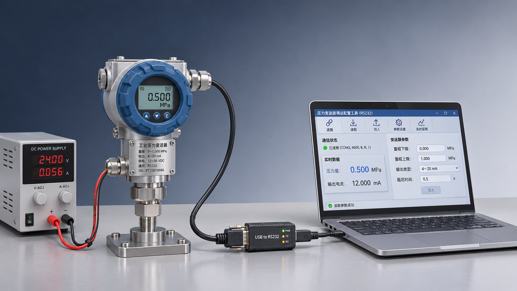
 Connecting an RS232 Pressure Transmitter to a Host Computer: Serial Port Parameters and Communication Troubleshooting
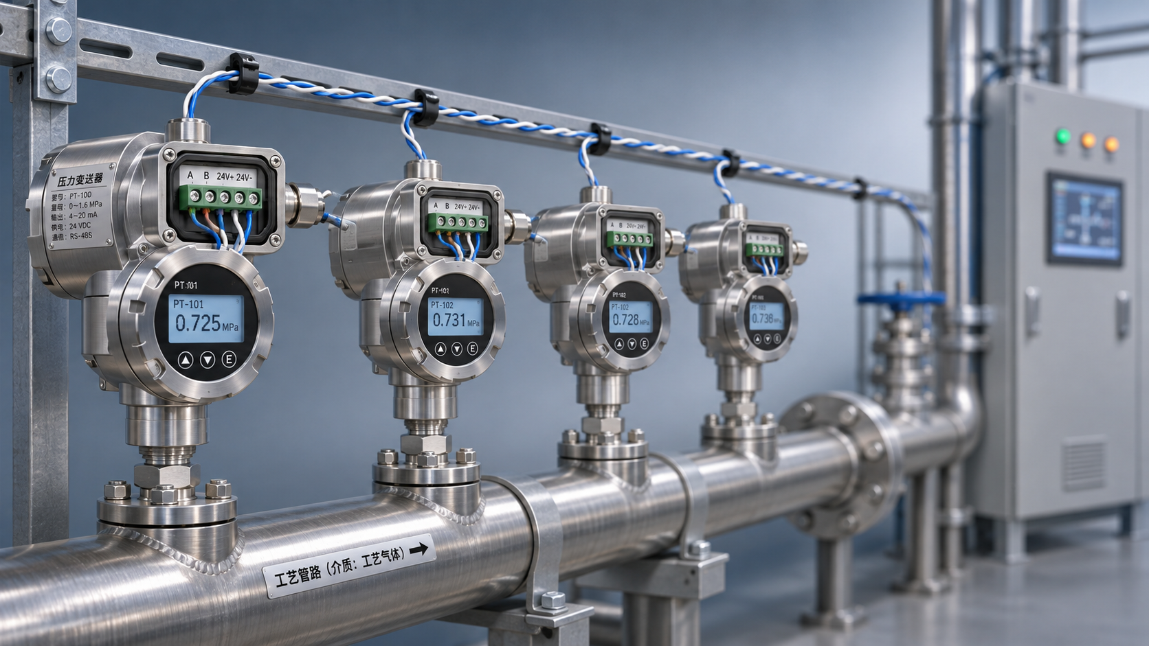
 RS485 Pressure Transmitter Multi-Drop Networking: How to Set the Terminating Resistor and Device Addresses?
 How Does a HART Pressure Transmitter Use an Overlay Signal for Remote Configuration?