


News Center
—— NEWS CENTER ——
Xi'an Shenghongchuang Instrument Co., Ltd.
Contact: Mr. Zhang
Mobile: 15529283736
Email: shc-sensor@qq.com
Address: Fortune Building, Sanqiao Street, Xixian New Area, Xi'an, Shaanxi Province
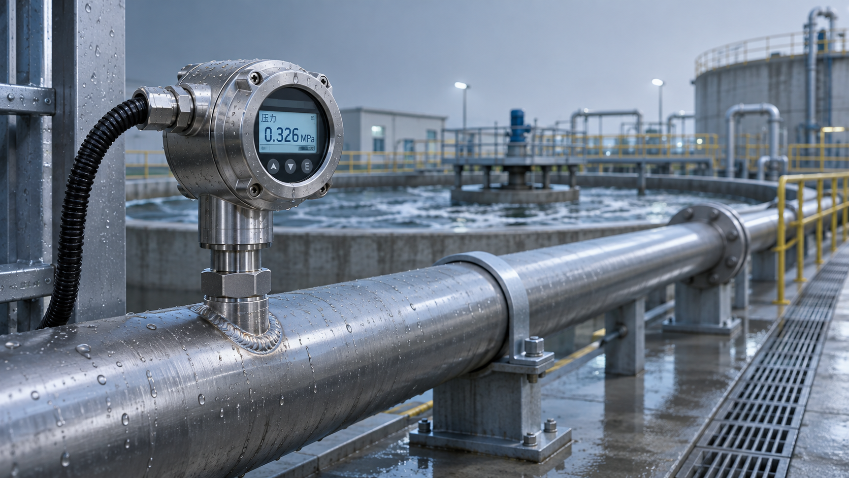
Sand, fibers, and flocculent matter in wastewater pipelines can easily accumulate at pressure tapping points, causing sluggish pressure signals, low readings, or readings that remain unchanged over time. The stable operation of an anti-clogging pressure transmitter depends not only on the instrument itself, but also on the pressure tapping design, installation location, and provisions for subsequent cleaning. Project managers should first distinguish between pipeline pressure monitoring and tank or basin level monitoring, then select a solution based on the properties of the medium and the site's maintenance capabilities.
I. First Identify the Cause of Clogging and the Measurement Task
Identify the Main Clogging Materials in Wastewater
Particles in wastewater containing sand can settle in narrow pressure tapping passages. Wastewater containing fibers can catch on openings, steps, or connections and gradually form blockages. Grease, sludge, and scale can also cover the diaphragm and slow the instrument's response.
Before selecting a model, determine the wastewater's particle size, solids content, temperature, corrosiveness, and flow-rate variations. Also consider whether pump start-ups and shutdowns, water hammer, or periodic sludge discharge occur. The media in an inlet channel, sludge return pipe, and chemical dosing pipe can differ significantly, so the same design should not be applied to all of them without evaluation.
Anti-clogging designs are intended to reduce sludge buildup and make cleaning easier; they do not guarantee that clogging will never occur under any wastewater operating condition. For media that are prone to entanglement or crystallization, or contain large particles, determine the cleaning interval based on on-site trial results.
Distinguish Between Pipeline Pressure and Tank or Basin Level
Pipeline pressure monitoring typically focuses on pump discharge pressure, pipeline network operating conditions, or pressure changes upstream and downstream of filtration equipment. Verify the operating pressure and instantaneous peak pressure at the installation point.
Tank or basin level monitoring commonly uses the hydrostatic pressure principle, converting liquid column pressure into a level reading. Changes in wastewater density, sediment covering the sensor, and flow within the tank or basin can all affect the measurement.
If both pipeline pressure and tank or basin level need to be monitored, verify the measuring range, process connection, and installation conditions for each instrument separately. Do not assume they are interchangeable based solely on descriptions such as “anti-clogging” or “pressure-type.”
II. Key Selection Considerations for Anti-Clogging Pressure Transmitters
Match the Design, Materials, and Measuring Range
For pipelines carrying sand-laden wastewater, consider flat diaphragms, flush diaphragms, or large-bore pressure tapping designs to reduce narrow passages and sludge-trapping dead zones. The specific design should be confirmed by the supplier and purchaser based on the pipe diameter, installation connection, and particle characteristics.
The diaphragm and other wetted parts should be made of materials compatible with the actual wastewater composition. 316L stainless steel is suitable for some common water-treatment media, but chloride concentration, pH, and temperature variations can all affect corrosion resistance. Suitability cannot be determined from the material name alone.
The measuring range should cover the normal operating pressure and potential pressure peaks, while also providing the required measurement resolution. For example, for a pipeline with a normal pressure of approximately 0.3 MPa, a 0–0.6 MPa range could be evaluated in light of the actual peak pressure. The final selection must still be based on water hammer calculations, overload capacity, and equipment documentation.
Consider the Signal, Power Supply, and Site Conditions
Wastewater treatment sites commonly use a 4–20 mA signal connected to a control system. When ordering, verify the supply voltage, wiring method, and control cabinet input type to avoid compatibility issues when the instrument arrives on site.
For outdoor, damp, or washdown locations, select an enclosure ingress protection rating based on the actual risk of water ingress, and check the overall protection provided by the cable glands, seals, and junction box. The enclosure rating does not replace the need to confirm the probe's immersion conditions.
Variable frequency drives, motors, and induced lightning surges can affect signal stability. During wiring, follow site requirements for shielding, grounding, and any necessary surge protection, and maintain appropriate separation from power cables.
III. Installation Location Determines Anti-Clogging Performance
Balance Representativeness and Maintainability When Selecting a Pipeline Pressure Tapping Point
The installation point should represent the pressure in the target pipeline section and avoid locations prone to sediment buildup, air pockets, or strong scouring. For horizontal pipelines, side pressure tapping can be evaluated in light of the medium flow direction and site experience. The specific orientation should be confirmed jointly based on the piping layout and with the instrument manufacturer.
Minimize long, narrow pressure tapping pipes, sharp bends, and unnecessary connection steps. If an isolation valve is required, verify that its bore is adequate for the medium to pass through and for maintenance. For high-solids applications, also allow space for removal, flushing, or draining.
Avoid positioning the diaphragm directly in the path of a high-velocity sand-laden jet for extended periods to reduce wear. Also avoid placing the measuring point in an obvious low-lying dead zone where sludge accumulates. For equipment subject to significant vibration, provide supports or vibration isolation in accordance with the instrument installation requirements.
On-Site Checks Before Installation
Verify the process connection size, pressure rating, and sealing method. Confirm that the gasket will not protrude after installation and create a new step where sludge can accumulate.
Check that there is sufficient working space nearby, and confirm the conditions for shutdown, isolation, depressurization, and draining. For work in confined spaces or involving hazardous media, follow site work-permit requirements.
After installation, check for leaks and verify the signal. Record the pressure, output value, and pump start/stop status during normal operation as a reference for identifying subsequent clogging and drift.
Keep Tank or Basin Level Measurements Clear of Sediment Zones
For submersible level measurement, the probe should not contact the tank or basin floor directly. Allow clearance based on the sludge accumulation height, and avoid locations near the inlet, agitators, or areas of intense aeration.
A guide tube or protective device can limit probe movement, but its openings, bore, and mounting method must not impede liquid flow or increase sludge buildup. For products with vented cables, protect the vent end from moisture and blockage as specified by the manufacturer.
For example, the domestic JCJ800S fire-water tank and reservoir level sensor can be used for related level measurement applications. Its listed range covers 0–0.5 m to 200 m of water column, and signal options include 4–20 mA. For wastewater projects, further confirm the anti-clogging design, wetted materials, immersion conditions, and ingress protection of the specific configuration. This level product should not be used as a direct replacement for a pipeline pressure transmitter without verification.
IV. Establish Practical Inspection and Maintenance Procedures
Detect Clogging Through Trend Changes
As a pressure tapping point gradually clogs, the pressure curve may become unusually flat, or its response to pump start-up and shutdown may be significantly delayed. Make a comprehensive assessment using a backup pressure gauge, equipment operating conditions, and historical trends to avoid mistaking actual operating changes for an instrument fault.
For newly commissioned projects, initially check for sludge buildup once a week. After the system has been operating for a period, adjust the interval based on the actual wastewater properties. This is a maintenance guideline and does not replace the requirements of the equipment manufacturer or site safety procedures.
Before cleaning, isolate the medium, confirm that the system is depressurized, and take appropriate protective measures. Clean the diaphragm according to the manufacturer's instructions. Do not scrape it with hard objects or force objects into the pressure tapping hole, as this may damage the diaphragm and sealing structure.
Compile Operating Conditions Before Purchasing
Project managers are advised to compile details in advance, including the measurement medium, particles and fibers, normal pressure, peak pressure, medium temperature, connection size, and required output signal. Also state whether the site allows shutdown for cleaning.
For wastewater tanks or basins, also provide the level range, bottom sediment conditions, installation depth, and cable routing. If corrosion protection, explosion protection, or special certifications are required, specify them separately and verify the relevant configuration and documentation.
Submit the above operating conditions and on-site installation photos to Xi'an Shenghongchuang Instrumentation Co., Ltd. Its technical staff can help verify the pressure tapping design, measuring range, and maintenance method before the configuration suitable for the project is finalized.
Related Recommendations
 Compensation Principles and Temperature Drift Parameters of Temperature-Compensated Pressure Transmitters
 Selecting a High-Temperature Liquid Pressure Transmitter: How to Determine Temperature, Sealing, and Range
 Sewage Containing Sand Easily Clogs Pipes? Installation and Selection Tips for Anti-Clogging Pressure Transmitters
 How Do You Evaluate a High-Stability Pressure Transmitter? Understanding Long-Term Drift and Temperature Effects