


News Center
—— NEWS CENTER ——
Xi'an Shenghongchuang Instrument Co., Ltd.
Contact: Mr. Zhang
Mobile: 15529283736
Email: shc-sensor@qq.com
Address: Fortune Building, Sanqiao Street, Xixian New Area, Xi'an, Shaanxi Province
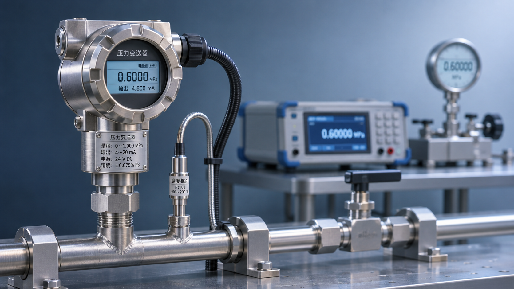
How can you evaluate a high-stability pressure transmitter? Start by examining long-term drift and temperature effects, then assess measurement reliability under actual operating conditions.
1. High stability does not mean high accuracy at delivery
A pressure transmitter performing well during factory calibration does not necessarily maintain the same error level after long-term operation. Once in service, the sensor’s sensitive elements, electronic circuits, and sealing structure are affected by factors such as time, temperature, pressure cycles, and the process medium. As a result, the output may gradually deviate from the initial calibration results.
Factory accuracy primarily reflects the overall error under specified conditions. Long-term stability describes how much the output changes over a period of time, while temperature effects concern output deviations as the ambient or process temperature changes. These three factors are related, but none can be used as a substitute for the others.
For example, if a transmitter with a range of 0–10MPa has a long-term stability specification of ±0.2%FS/year, this corresponds to ±0.02MPa of full scale. When assessing this figure, also confirm the test conditions, applicable range, and statistical basis. It should not be treated as a fixed error that necessarily occurs every year.
Evaluating a high-stability pressure transmitter requires consideration of its specifications, the site environment, and the maintenance interval. For measurement points that operate continuously for long periods, are difficult to shut down for calibration, or have limited control margins, comparing only purchase price and factory accuracy is often not enough.
2. Assess long-term drift by examining both the specification and its verification conditions
1. Understand how drift is expressed
Long-term drift is usually expressed as a percentage of full scale, together with a time period, such as ±0.1%FS/year. FS stands for full scale or span; refer to the manufacturer’s documentation for the specific calculation basis. Before comparing different products, standardize the range, time period, and reference conditions.
The same specification of ±0.1%FS/year corresponds to ±0.001MPa for a 0–1MPa range and ±0.01MPa for a 0–10MPa range. The larger the range, the greater the pressure change represented by the same percentage. Therefore, figures should not be compared without considering the actual operating pressure.
Also distinguish between a “typical value” and a “maximum value.” A typical value describes common product performance and should not be treated as a guaranteed upper limit for every device. A maximum value should also be interpreted in light of the manufacturer’s specified conditions of applicability. When setting acceptance criteria or maintenance intervals, confirm which value is specified in the contract and technical documentation.
Manufacturers may define long-term zero drift, span drift, and overall stability differently. Before purchasing, request the test method, measurement points, test period, and environmental conditions to avoid comparing figures based on different definitions.
2. Use periodic calibration records to assess trends
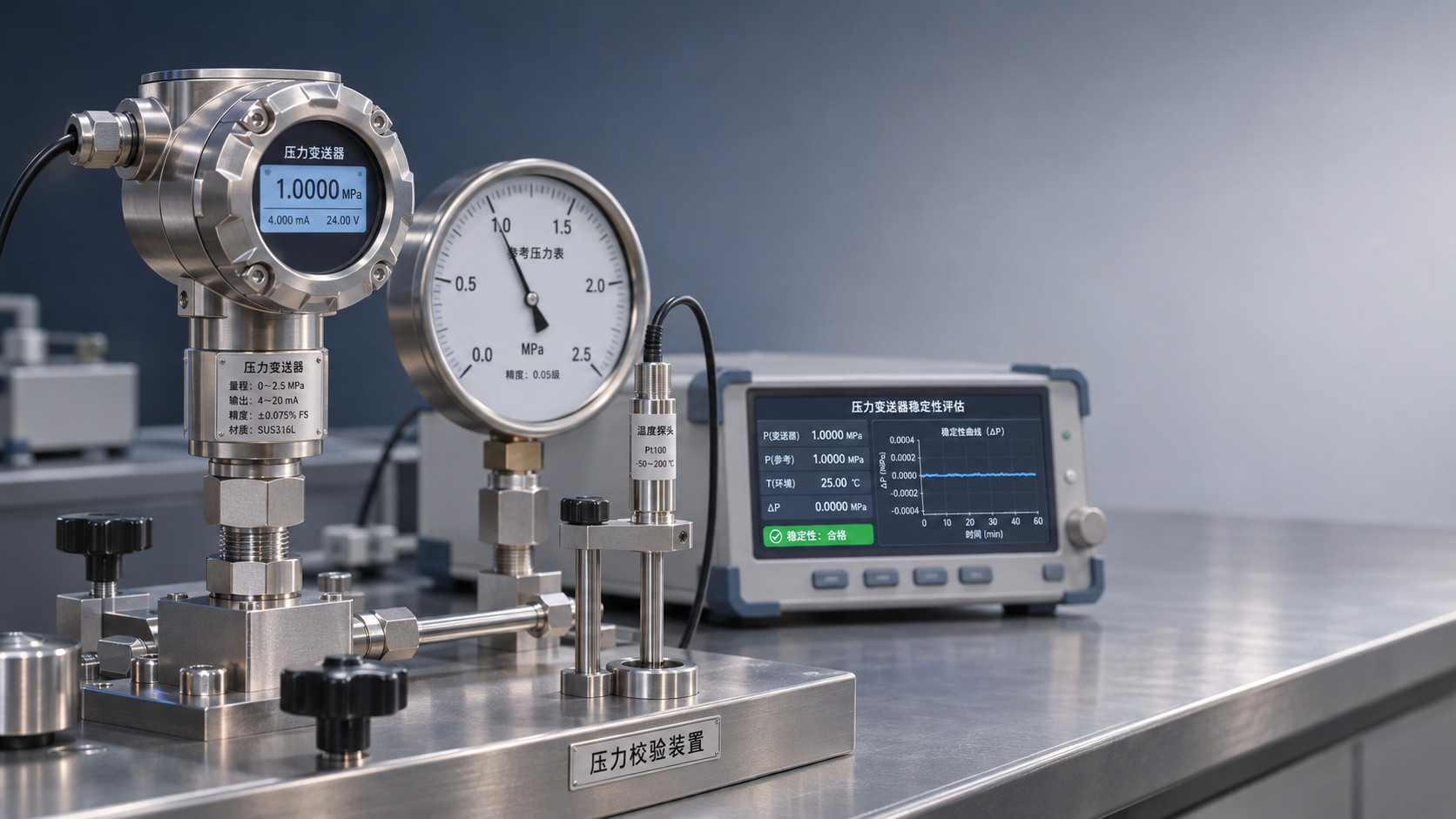
For field verification, retain the baseline record from commissioning and, during subsequent calibration, use the same pressure points, mounting orientation, and stable temperature whenever possible. A common approach is to record the output at zero and at several range points, then compare it with a reference standard to check whether the deviation increases over time.
Calibration records should include not only error values, but also ambient temperature, power supply status, process medium conditions, and whether the zero point has been adjusted. After zero adjustment or recalibration, retain both pre- and post-adjustment data; otherwise, the device’s original drift trend may be obscured.
If the deviation suddenly increases during just one calibration, first check for blockage, overpressure, loose wiring, and the condition of the reference standard. If it continues to move in the same direction over multiple calibration cycles, assess the operating conditions to determine whether to shorten the calibration interval or replace the device.
The calibration interval should not be determined solely by the figure for annual drift. The importance of the measurement point, allowable error, historical records, and site management requirements all affect the interval. Maintenance frequency for critical control points should generally be determined more cautiously.
3. Assess temperature effects in relation to the compensation range
1. Distinguish between process temperature, ambient temperature, and compensation temperature
Process temperature is the temperature of the liquid, gas, or steam being measured, while ambient temperature is the temperature around the transmitter’s location. The two can differ significantly. Even if the air temperature is not high at a measurement point near a hot pipeline, considerable heat may still be transferred through the process connection.
The temperature compensation range is the range over which the product compensates for temperature characteristics; it is not necessarily the same as the permissible ambient operating temperature range. The fact that a device can operate within its permissible temperature range does not automatically mean it will perform the same throughout that range.
When reviewing temperature drift parameters, confirm whether they include zero effects, span effects, or both. Also check whether the value is specified per degree Celsius or as the total change over a particular temperature range. Figures presented in different ways cannot be compared directly by their numerical values alone.
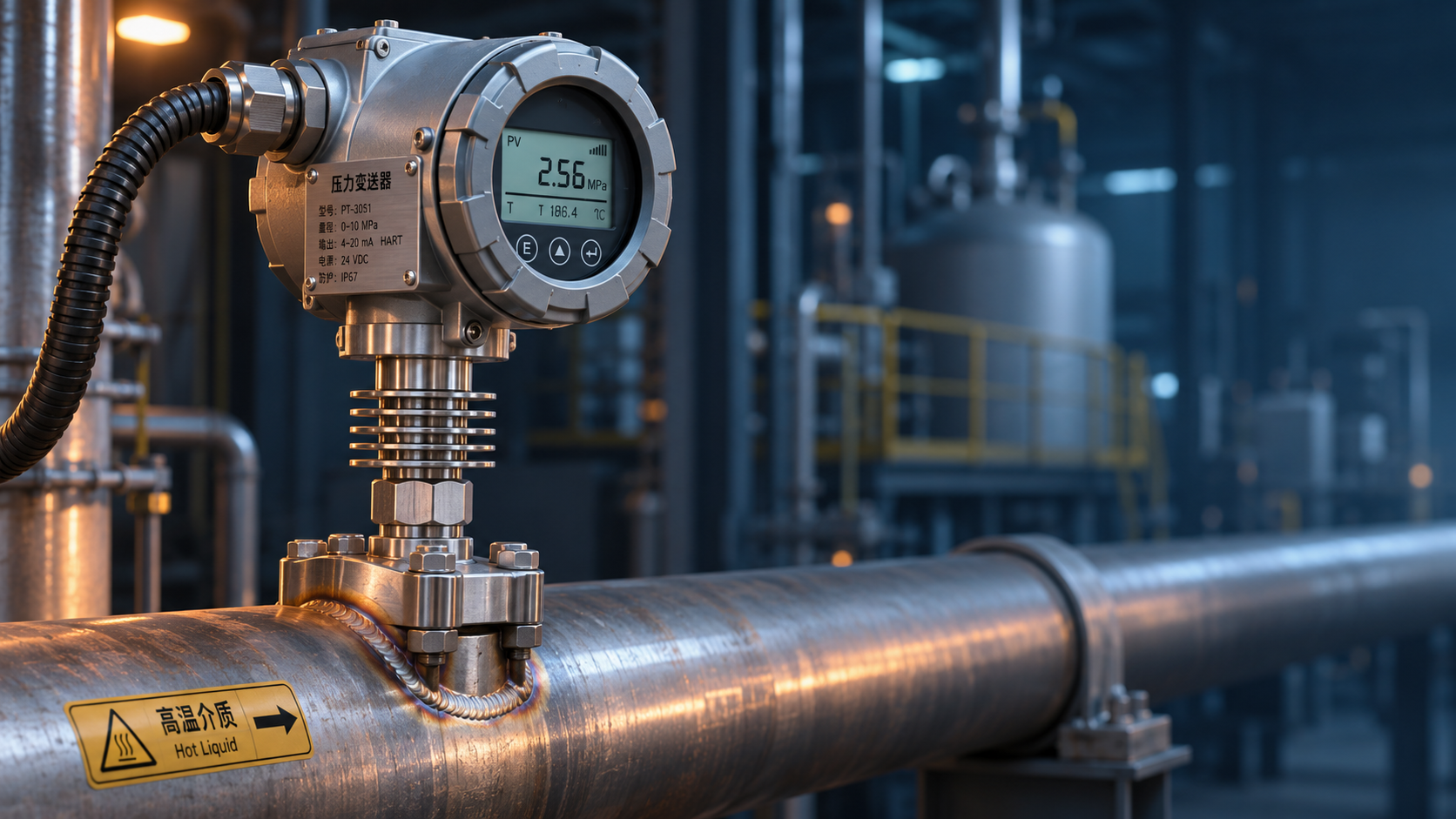
For measurement points exposed to high temperatures or large temperature differences, also confirm with the manufacturer the actual temperature experienced by the sensor body and whether a cooling coil, insulation, or installation away from the heat source is required. The suitability of accessories must be assessed in light of the process medium, pressure, and site safety requirements.
Example of estimating temperature-related deviation
Assume a product is specified with temperature drift of no more than ±0.05%FS/℃, and the manufacturer confirms that this coefficient applies to the temperature change and error calculation method under consideration. If the temperature changes by 10℃ relative to the reference condition, a linear estimate based on the coefficient gives a potential effect of up to ±0.5%FS.
For a range of 0–10MPa, ±0.5%FS corresponds to ±0.05MPa. This is a conservative example based only on the stated coefficient. It does not mean the device will show this deviation at all temperatures, nor does it replace the manufacturer’s actual temperature characteristic data.
Temperature effects may also occur alongside long-term drift and calibration error. Their directions and correlations are not necessarily the same, so they should not be assumed to add fully or cancel each other out. When preparing an error budget, select an appropriate method based on the specification definitions, risk requirements, and reliability of the available data.
If there are significant temperature differences between morning and evening at the site, observe output changes under representative low-, high-, and normal-temperature conditions, while ruling out actual pressure fluctuations. For level measurement, also consider additional effects caused by changes in process-medium density with temperature.
4. Compare specifications and select a model based on the application
When selecting a model, first determine the actual pressure range, allowable error, and process conditions, then compare long-term stability and temperature specifications. Do not select a range solely to cover the maximum pressure; also consider where the normal operating point falls within the range, as well as the risks of pressure surges and overload.
The table below lists commonly used evaluation criteria. Manufacturers may define specifications differently, so the technical documentation for the relevant model and the selection documents confirmed by both parties should be treated as authoritative.
For example, the YLT201B General-Purpose Pressure Transmitter from China, Medium- and High-Temperature Pressure Sensor offers multiple pressure ranges and standard signal options, and can be used in applications such as hydraulic systems, pneumatic systems, constant-pressure water supply, and industrial process monitoring. The specific configuration should be confirmed based on the measurement point conditions.
The published specifications for this model list a typical stability value of ±0.1%FS/year and a maximum value of ±0.2%FS/year. Temperature drift is ≤±0.05%FS/℃, and the specification covers temperature effects on both zero and span. When selecting the model, confirm the test conditions and the specific applicability of these specifications with the manufacturer.
5. Move from document review to on-site management
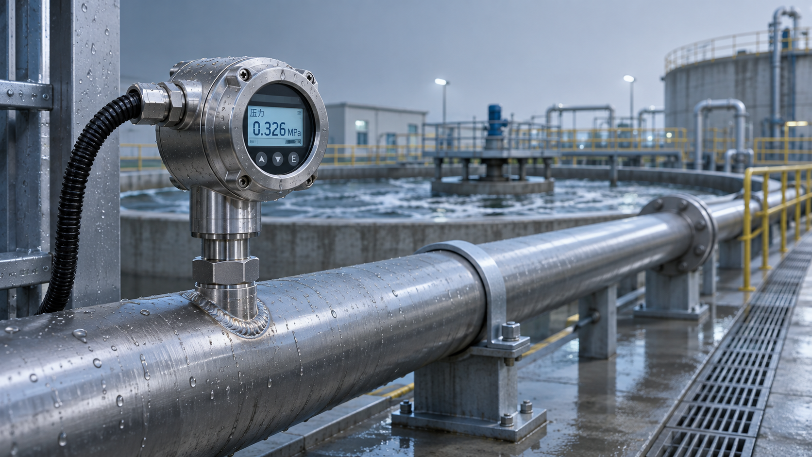
Stable operation depends on correct installation. Select appropriate pressure connections, sealing materials, and installation locations according to the process medium and requirements. Avoid measurement interference caused by vibration, condensation, blockage, or pressure pulsation. The suitability of 304 or 316 stainless steel wetted parts should also be assessed based on the medium’s composition, concentration, and temperature.
For electrical requirements, verify the output type, supply voltage, and control-system input requirements, and handle shielding, grounding, and cable routing in accordance with site standards. The product’s ingress protection rating must also be checked against the specific electrical connection type; do not assume all connector configurations provide the same level of protection.
For critical measurement points, maintain records covering the model, range, installation location, initial calibration results, and maintenance history. Adjusting the calibration plan based on actual deviation trends is more helpful for ensuring measurement reliability than relying solely on the claim of “high stability.”
To assess a specific measurement point, provide Xi’an Shenghongchuang Instrumentation Co., Ltd. with the medium name, normal and maximum pressure, process and ambient temperatures, required output signal, and allowable error. Its technical staff can help verify the range, materials, and installation configuration.
Related Recommendations
 Compensation Principles and Temperature Drift Parameters of Temperature-Compensated Pressure Transmitters
 Selecting a High-Temperature Liquid Pressure Transmitter: How to Determine Temperature, Sealing, and Range
 Sewage Containing Sand Easily Clogs Pipes? Installation and Selection Tips for Anti-Clogging Pressure Transmitters
 How Do You Evaluate a High-Stability Pressure Transmitter? Understanding Long-Term Drift and Temperature Effects