News Center
—— NEWS CENTER ——
Xi'an Shenghongchuang Instrument Co., Ltd.
Contact: Mr. Zhang
Mobile: 15529283736
Email: shc-sensor@qq.com
Address: Fortune Building, Sanqiao Street, Xixian New Area, Xi'an, Shaanxi Province
Measuring Liquid Level with a Dual-Flange Differential Pressure Sensor: Where Do Errors Under High-Temperature Conditions Come From?
A dual-flange differential pressure sensor uses two remote seal assemblies connected respectively to the bottom and top pressure taps of a vessel, and calculates the liquid level by comparing the pressure difference between the two sides. For closed vessels, the basic relationship is: the differential pressure is approximately equal to the product of medium density, gravitational acceleration, and liquid level height, i.e., ΔP≈ρgh. High-temperature media do not change this measurement principle, but they do alter the actual operating conditions of the fill fluid, capillaries, and isolation diaphragms involved in pressure transmission.
An instrument that passes calibration at ambient temperature may exhibit zero drift, amplified liquid level fluctuations, or increased full-scale deviation after being put into a high-temperature field application. This is usually not a single sensor fault, but the result of combined thermal effects. Particularly in applications such as steam-jacketed vessels, reactors, thermal oil storage tanks, and polymerization equipment, temperature changes are often accompanied by pressure fluctuations, changes in medium density, and uneven equipment wall temperatures. These factors must be evaluated together.
The advantage of a dual-flange configuration is that the isolation diaphragms can directly contact the process medium, preventing high-viscosity, crystallizable, or clogging media from entering impulse lines. However, the two capillaries are usually filled with silicone oil, inert fill fluid, or dedicated high-temperature seal fluid. As temperature rises, the fill fluid expands in volume and creates additional pressure through the diaphragms and the sensor measuring chamber. This is one of the main sources of high-temperature liquid level measurement errors.
Therefore, reducing errors cannot rely solely on subsequent “zero adjustment.” A more effective approach is to first select the remote seal system according to the actual temperature, pressure, range, and installation distance, then control thermal gradients through symmetrical installation, and finally conduct verification and compensation based on the actual liquid level under stable operating conditions.
Main Effects of High Temperature on Dual-Flange Differential Pressure Measurement
Additional Static Pressure Error Caused by Thermal Expansion of Fill Fluid
The longer the capillary, the greater the volume of fill fluid inside it, and the more pronounced the total expansion during temperature changes. If the capillaries on the high-pressure and low-pressure sides are heated unevenly, their expansion amounts will differ. The sensor will identify this difference as a differential pressure change, ultimately resulting in liquid level reading drift. For small-range liquid level measurements, such as applications with ranges of only 5 kPa or 10 kPa, even a small additional differential pressure can cause a significant percentage error.
At high temperatures, it is not sufficient to simply assume that meeting the temperature resistance requirement is enough. The upper temperature limit of the fill fluid only indicates that it will not fail rapidly; it does not mean ideal accuracy can still be achieved at that temperature. When selecting a model, temperature effect specifications for the remote seal system should also be reviewed, with particular attention to ambient temperature effects, process temperature effects, capillary length correction factors, and zero suppression/elevation range.
A common engineering practice is to keep the length of each capillary within 3 m to 5 m where installation conditions permit. When longer capillaries are unavoidable, priority should be given to low-thermal-expansion fill fluids, larger diaphragm volumes, or high-temperature remote seal solutions calculated by the manufacturer. The length difference between the two capillaries should be kept as small as possible, typically within 100 mm.
For batch reaction processes where temperature may change by tens of degrees Celsius within a short period, dynamic thermal drift should also be considered. The instrument output may temporarily deviate from its stable value during heating or cooling. In such cases, appropriate damping should be set in the control system, typically from 3 s to 15 s depending on process response, to avoid mistaking thermal transients for actual sudden liquid level changes.
Range Deviation Caused by Process Temperature and Medium Density Changes
The basis of differential pressure liquid level measurement is the hydrostatic pressure of the medium, which is directly affected by density. Many liquids decrease in density as temperature rises, causing the differential pressure generated by the same actual liquid level to decrease accordingly. If the transmitter range is still set according to ambient-temperature density, the indicated liquid level may be lower than the actual liquid level. This type of deviation cannot be eliminated merely by a one-time zero adjustment.
For example, if a liquid has a density of 950 kg/m³ at 20℃ and drops to 850 kg/m³ at 180℃, the density change is approximately 10.5%. For a liquid level system calibrated based on ambient-temperature density, the theoretical conversion error near full liquid level may also approach 10% if no compensation is applied. Therefore, the medium density at normal operating temperature should be used as the basis for range calculation.
If the process temperature range is wide, for example from 80℃ to 250℃, and density varies significantly with temperature, the temperature signal can be introduced into the DCS or PLC for real-time compensation according to the medium density-temperature curve. For media with unstable density variation, frequently adjusted formulations, or significant changes in gas content, it should be reassessed whether the differential pressure method remains the most suitable liquid level measurement solution.
Before engineering delivery, four data points should be clearly defined: “calibration density,” “minimum density,” “maximum density,” and “normal operating density.” Including the full-scale differential pressure corresponding to the minimum density in model selection verification can prevent insufficient effective resolution caused by excessively low actual differential pressure during operation, and also provide a reliable basis for setting alarm and interlock points.
Key Parameters to Control During Model Selection
Select Diaphragms, Flanges, and Fill Fluid According to Temperature Rating
The isolation diaphragm material must meet temperature resistance, corrosion resistance, and mechanical strength requirements at the same time. 316L stainless steel is suitable for various conventional high-temperature media. For media containing chloride ions, strong acids, strong alkalis, or special solvents, materials such as Hastelloy, tantalum, and nickel-based alloys may be considered. Material selection must be based on medium composition, concentration, temperature, and pressure, and cannot be determined solely by corrosion resistance at ambient temperature.
Flange standards, sealing face types, and insertion lengths also affect measurement stability. For equipment with thick vessel walls or thick insulation layers, flange nozzle dimensions need to be verified in advance to prevent the isolation diaphragm from being positioned away from the inner vessel wall and creating a stagnant area. If material accumulates, cokes, or crystallizes near the diaphragm, pressure transmission sensitivity will be reduced and the liquid level signal may exhibit hysteresis.
Fill fluid selection should be determined jointly by the maximum process temperature, minimum temperature, vacuum conditions, sanitary requirements, and response speed. A temperature margin should be reserved for high-temperature applications, and long-term operation close to the maximum rated temperature of the fill fluid or remote seal assembly should be avoided. For example, if the normal process temperature is 280℃, selection should focus on confirming the long-term stability of the system above 300℃ rather than considering only short-term temperature resistance data.
For vacuum or negative-pressure vessels, the diaphragm's resistance to negative pressure must also be verified. After the equipment is shut down and cools following a temperature increase, a vacuum may form inside. If the remote seal system is not designed for vacuum conditions, the diaphragm may undergo irreversible deformation, causing permanent zero drift. When high temperature and vacuum coexist, both conditions should be included in the technical specification.
Installation Arrangement Determines High-Temperature Measurement Stability
Keep Both Remote Seal Systems in the Same Thermal Environment
The core installation principle for a dual-flange differential pressure sensor is symmetry. The two capillaries should be as close as possible in length, routing, and fixing method, avoiding a situation where one side is close to a high-temperature equipment wall while the other is exposed to a ventilated area. If the thermal histories of the two sides differ, even using the same type of fill fluid will result in continuous deviation due to different expansion states.
Capillaries should preferably be installed parallel to the equipment surface. Depending on site vibration conditions, the spacing between fixing points can be controlled at approximately 0.5 m to 1 m to avoid unsupported swinging, stress from bending, or local compression. The bend radius should comply with manufacturer requirements. Sharp bends must not be formed merely to shorten the route, otherwise the internal capillary may be damaged or the stress state of the sealing system may be altered.
When the vessel is equipped with steam tracing or electric heat tracing, capillaries generally should not be directly bundled with tracing lines. Where anti-condensation or anti-crystallization is necessary, a calculated uniform insulation solution should be adopted so that the high-pressure and low-pressure sides are heated simultaneously and local temperature differences are minimized. Direct localized intense heating often causes more severe zero drift.
The transmitter body should be installed in a location with relatively stable ambient temperature and convenient maintenance access, away from furnace radiation zones and high-temperature steam exhaust outlets. Even if remote seal flanges can withstand high temperatures, electronic components remain subject to ambient temperature limitations. It should generally be confirmed that the site ambient temperature does not exceed the specified instrument value. If necessary, install a heat shield, ventilation cover, or mounting bracket away from heat sources.
Avoid Common Installation Errors
Reversing the high-pressure-side and low-pressure-side flanges will cause the liquid level display direction to be incorrect. For closed tanks with negative elevation, it may also cause commissioning personnel to mistakenly identify the issue as a parameter setting problem. After installation, verify against the process diagram that the lower flange corresponds to the high-pressure side and the upper flange corresponds to the low-pressure side, and check the transmitter port markings.
If the upper flange is installed where condensate can easily accumulate, the top reference pressure will no longer represent only gas-phase pressure, as the liquid column will create additional static pressure. For high-temperature steam or easily condensable media, an appropriate pressure tapping location should be selected based on the vessel structure. Other measurement configurations should be used where necessary, while avoiding dead zones in front of the remote seal diaphragm.
The inner diameter of the flange gasket must not obstruct the effective pressure-receiving surface of the isolation diaphragm. During installation, bolts should be tightened evenly in a diagonal sequence to avoid uneven stress near the diaphragm caused by excessive tightening on one side. During maintenance, disassembly, and installation, hard objects must not touch the diaphragm surface, as even minor scratches may affect long-term stability.
After equipment insulation construction is completed, check again whether the capillaries have been flattened, excessively covered, or affected by a heat source on one side. Many on-site thermal drift issues do not occur during initial instrument installation, but gradually emerge after insulation is added, heat tracing is modified, or equipment layout is adjusted. Therefore, reinspection after modification is essential.
Calibration, Compensation, and Operation Maintenance Methods
Complete Commissioning Based on Stable Process Conditions
Final zero calibration of high-temperature liquid level systems should not be performed immediately after equipment heating, shutdown, or during severe temperature fluctuations. The actual liquid level and output signal should be compared only after the temperatures of the vessel, flanges, capillaries, and surrounding transmitter environment have stabilized. For large reaction equipment, the thermal stabilization process may take several hours, and confirmation should be completed within a stable operating window permitted by the process.
During calibration, in addition to checking the zero liquid level corresponding to 4 mA and the full liquid level corresponding to 20 mA, at least three intermediate points at 25%, 50%, and 75% should be verified. If both the zero and full-scale points are correct but the intermediate points show obvious deviation, medium density settings, linear conversion, and actual installation height should be checked first rather than blindly and repeatedly adjusting the range.
For closed vessels, transmitter range settings must account for the installation height difference between the upper and lower flanges, capillary system shift, and process design pressure range. Engineering personnel should retain the original calculation sheet, including design liquid level height, operating density, minimum and maximum differential pressure, shift direction, and output correspondence. This allows subsequent maintenance personnel to quickly determine whether a deviation is caused by an instrument issue or a process condition change.
During operation, differential pressure liquid level readings can be periodically cross-checked against on-site sight glass level gauges, radar level gauges, or material balance results. If deviations vary with day-night ambient temperature changes, focus should be placed on checking whether the capillaries are exposed to sunlight, locally air-cooled, or unevenly heat traced. If deviations change regularly with process temperature, the density compensation model should be reviewed.
Implementation Recommendations for High-Temperature Liquid Level Projects
When dual-flange differential pressure sensors are used for high-temperature liquid level measurement, accuracy depends on system design, not just transmitter accuracy. Prioritizing shorter and symmetrically arranged capillaries, selecting diaphragms and fill fluids compatible with the temperature and medium, and calculating the range based on actual operating density are the three fundamental measures for controlling errors.
For projects involving high temperatures, small liquid level ranges, large density fluctuations, or complex equipment structures, the medium name, maximum temperature, normal temperature, operating pressure, vacuum conditions, density range, flange standard, center distance, and estimated capillary length should be provided before ordering. Complete operating condition data can help technical personnel calculate shift, differential pressure range, and thermal drift risk.
Xi'an Shenghongchuang Instrumentation Co., Ltd. can provide dual-flange differential pressure liquid level sensor selection, remote seal configuration matching, range calculation, and commissioning recommendations based on site conditions for reactors, storage tanks, evaporators, thermal oil equipment, and other applications. Targeted technical confirmation can also be provided for non-standard flanges, special diaphragm materials, high-temperature fill fluids, and complex installation distances.
To reduce existing high-temperature liquid level measurement errors, on-site temperature curves, vessel drawings, current instrument models, capillary arrangement photos, and actual deviation data can be compiled. Professional technical personnel can then verify the selection, installation, and parameter settings item by item to develop an actionable optimization solution.
Related Recommendations
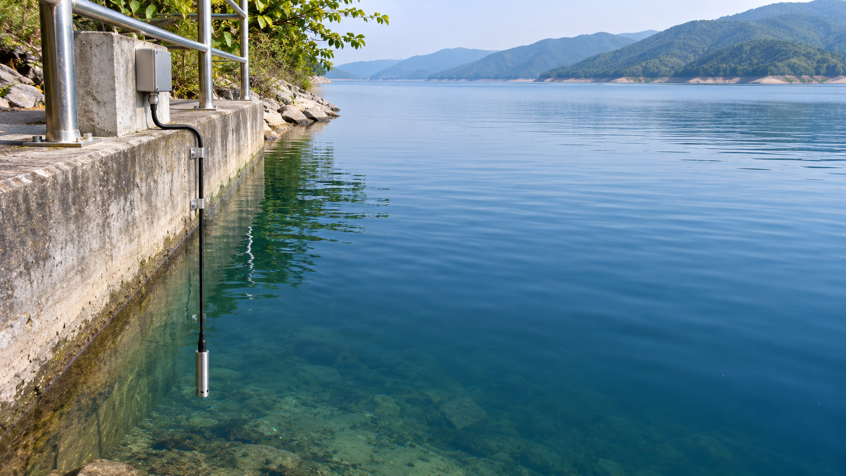
 What Can Hydraulic Pressure Transmitters Measure? Applications from Reservoir Water Levels to Pipeline Pressure
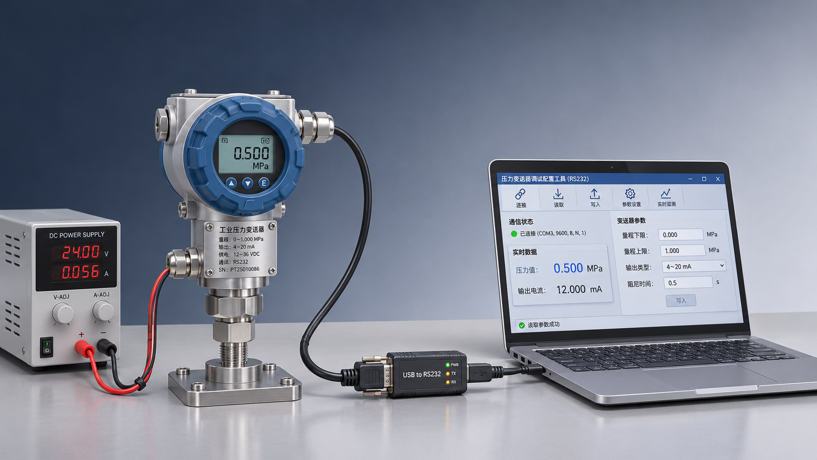
 Connecting an RS232 Pressure Transmitter to a Host Computer: Serial Port Parameters and Communication Troubleshooting
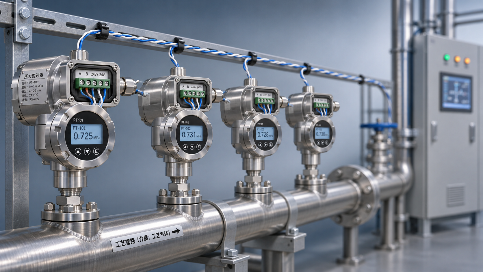
 RS485 Pressure Transmitter Multi-Drop Networking: How to Set the Terminating Resistor and Device Addresses?
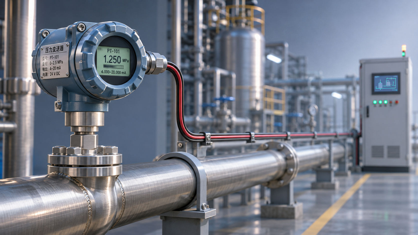
 How Does a HART Pressure Transmitter Use an Overlay Signal for Remote Configuration?