News Center
—— NEWS CENTER ——
Xi'an Shenghongchuang Instrument Co., Ltd.
Contact: Mr. Zhang
Mobile: 15529283736
Email: shc-sensor@qq.com
Address: Fortune Building, Sanqiao Street, Xixian New Area, Xi'an, Shaanxi Province
Two-Wire and Four-Wire Level Sensors: Focus on the “Loop” Rather Than the Number of Wires
What makes a two-wire level sensor better than a four-wire one? The answer is not absolute “better performance,” but rather that, in most standard analog measurement applications, it can use fewer conductors to complete power supply and signal transmission, making field wiring simpler and installation and subsequent maintenance costs easier to control. Especially in projects with dispersed measurement points, such as storage tanks, wells, pipe galleries, and wastewater treatment plants, two-wire 4-20mA solutions offer clear engineering convenience.
Two-wire systems typically use loop-powered operation: a 24VDC power supply powers the instrument through the same pair of wires, while the sensor reflects level changes through a 4-20mA current. 4mA generally corresponds to the lower range limit, and 20mA corresponds to the upper range limit. For example, for a 0-5m level range, when the liquid level is 2.5m, the ideal output is approximately 12mA, which the control system can use for display conversion, alarms, or interlock control.
Four-wire products commonly separate the power supply loop from the output loop, with two wires used for power input and the other two used for analog, frequency, voltage, or other signal outputs. They can provide sufficient power and more flexible interface conditions for certain high-power measurement units, signal processing modules, or special output types, but cable, terminal, and wiring inspection work also increases accordingly.
Therefore, the key to selection should not be limited to “two wires or four wires,” but should be determined by considering the measurement principle, power supply conditions, control cabinet interfaces, transmission distance, medium characteristics, and on-site electromagnetic environment. The level transmitters and supporting intelligent digital display control instruments manufactured by Shaanxi Qinkong Sensor Technology Co., Ltd. can provide suitable measurement and control solutions for conventional or complex operating conditions.
Key Advantages of Two-Wire Level Sensors
Reduced Wiring for More Efficient Project Implementation
The most direct advantage of a two-wire system is reduced cable usage. For a single measurement point, changing from a 4-core cable to a 2-core shielded cable may appear to save only 2 cores; however, when a project includes 50, 100, or even more level measurement points, cable tray occupancy, cable procurement, wiring labor hours, and the number of terminals all decrease accordingly.
This advantage is even more evident in retrofit projects. When an old plant has limited control cabinet space, congested existing cable trays, or small embedded conduit diameters, two-wire systems can reduce the impact of additional wiring on existing facilities. For dispersed storage tanks located 300m, 500m, or more from the control room, two-wire systems can still be applied reliably as long as the calculated loop voltage drop meets the instrument's minimum operating voltage requirement.
Fewer wiring points also mean fewer potential fault points. In industrial environments, issues such as looseness, oxidation, poor crimping, and reversed polarity often occur at terminals. Reducing the number of main wiring terminals from 4 to 2 makes installation acceptance and troubleshooting more straightforward, making this solution particularly suitable for automated production lines and warehouse level monitoring systems requiring large-scale deployment.
4-20mA Signals Are Suitable for Industrial Long-Distance Transmission
Two-wire level transmitters are typically used with 4-20mA signals. Compared with voltage signals such as 0-10V, current signals are less sensitive to changes in line resistance and are better suited to long-distance transmission in industrial environments. With appropriate power supply, cable, and load configurations, transmission distances of several hundred meters are common; the actual distance should still be calculated based on the supply voltage and total loop load.
The 4mA “live zero” also provides basic fault identification value. A normal zero level is not 0mA but 4mA; when the loop is disconnected, the instrument loses power, or wiring becomes detached, the control system can generally identify an abnormal current significantly below the normal range. Some systems also set below 3.6mA and above 21mA as fault or over-range diagnostic intervals.
However, interference resistance does not mean wiring practices can be ignored. Strong electromagnetic interference near frequency converters, motors, contactors, and high-power cables can still affect loop stability. In engineering applications, shielded twisted-pair cable should be used, signal cables should be routed separately from power cables or kept at an appropriate distance, and shielding layers should be handled in accordance with system grounding specifications to avoid interference loops caused by multi-point grounding.
Four-Wire Systems Are Not Outdated: When They Are Worth Choosing
High Power Consumption or Extensive Functional Integration Requirements
Some level measurement devices contain displays, buttons, relays, multiple outputs, communication modules, or relatively complex signal processing units. Their operating power consumption may exceed the capacity available from conventional two-wire loops. In such cases, a four-wire configuration with an independent power supply makes it easier to ensure stable operation of the device with all functions enabled.
For example, if a device must output a continuous 4-20mA level signal, provide high- and low-level relay alarms, and connect to an RS485 communication network, the product's actual wiring definition must first be confirmed. Its functions cannot be determined solely by the fact that it has 4 wires, nor can the signal terminals of a four-wire system be used directly as two-wire loop terminals.
When the on-site control system already provides an independent 24VDC power supply and separate signal input terminals, and cable resources are sufficient, the installation cost of a four-wire system may not increase significantly. In such scenarios, greater attention should be given to sensor range, accuracy, material, protection rating, and medium compatibility, rather than simply pursuing a reduction of two wires.
Special Outputs and High-Accuracy Applications Require Specification Verification
Four-wire systems do not inherently provide higher accuracy, nor do two-wire systems imply insufficient accuracy. Level measurement accuracy is mainly affected by the sensing principle, temperature drift, installation position, changes in medium density, fluctuation conditions, calibration method, and signal processing capability. For pressure-based level measurement, liquid density and atmospheric pressure compensation conditions must also be considered.
If a project requires accuracy of 0.5%FS, 0.25%FS, or a higher grade, the complete technical documentation should be reviewed for overall accuracy, long-term stability, temperature drift specifications, and calibration conditions. For a 10m range with 0.5%FS, for example, the theoretical basic error is approximately plus or minus 50mm; actual system error will also include installation and operating condition factors.
For frequency, voltage, RS485, or other digital communication outputs, the wiring logic for power supply and signals may differ from conventional 4-20mA systems. Before procurement, the supplier should confirm the operating voltage range, maximum load, recommended cable length, terminal diagram, and system compatibility to avoid instrument damage or abnormal data caused by wiring based on general experience.
From Installation Cost to Operational Reliability: Complete Selection According to Operating Conditions
First Calculate the Available Loop Power Margin
Before selecting a two-wire system, verify the transmitter's operating voltage range, such as 12-36VDC or 10-30VDC, as well as the input resistance of the receiving device. The total loop voltage drop includes cable resistance, PLC or digital display input load, and voltage drops across other series-connected devices. Even under the most unfavorable conditions, the voltage at the sensor terminal must remain above the minimum operating voltage.
A common 250 ohm resistor can convert 4-20mA into a 1-5V signal, with a voltage drop of 5V at 20mA. When long-distance cable voltage drop is added, a 24VDC system usually still has a certain margin, but the calculation must not be omitted. For particularly long lines or applications with series-connected isolators and surge protectors, technical personnel should verify the configuration based on actual parameters.
In humid environments, 24VDC level sensors can be used, but an enclosure and electrical protection structure suitable for the environment should be selected. For outdoor water tanks, underground pump rooms, and similar locations, special attention should be given to cable entry devices, junction box sealing, installation orientation, and drip loops to prevent condensate from entering the housing along the cable, rather than focusing only on the rated voltage.
Additional Considerations for Viscous Media and Control Loads
For viscous liquids, media containing suspended solids, or media prone to crystallization, the key to preventing blockage in level sensors lies in the process connection and installation position. Structures likely to create dead zones should be avoided. Where necessary, flush diaphragms, flange mounting, diaphragm seals, or structures that are easy to disassemble and clean should be used, and the measuring surface should avoid stirring vortices, material feed impact, and sedimentation areas.
Whether a relay-output level sensor can directly control a water pump depends on the relay contact rating and the pump's starting current. Small loads can be controlled within the rated range, but the starting current of most motors is much higher than the running current. In engineering practice, isolation is usually achieved through an AC contactor, intermediate relay, or variable frequency drive control terminal; sensor contacts should not be allowed to withstand motor surge currents directly over extended periods.
Industries such as food, pharmaceuticals, and coal mining also have compliance requirements. For food-contact applications, relevant documentation must be confirmed based on wetted materials, hygienic design, and customer system requirements. For level equipment used underground in coal mines, coal mine safety, explosion-proof, and other qualifications must be verified according to the specific area of use and regulatory requirements. Certification requirements are not directly determined by the wiring configuration and must be confirmed item by item according to the industry, location, and method of use.
Conclusion: Prioritize Two-Wire Systems for Standard Remote Transmission and Choose Four-Wire Systems for Special Requirements
For most projects using PLC, DCS, or intelligent digital display instruments for continuous level monitoring, two-wire 4-20mA level sensors offer advantages in wiring efficiency, long-distance transmission suitability, fault identification, and overall installation cost, making them a mature and widely applicable choice in industrial automation.
When equipment requires independent power supply, multiple outputs, relay control, communication functions, or when the sensing unit has high power consumption, four-wire solutions are better able to meet functional and power margin requirements. The two configurations are not simply interchangeable; the correct approach is to match the signal type, power supply conditions, and on-site operating conditions.
Xi'an Shenghongchuang Instrumentation Co., Ltd. can provide selection support for level transmitters and intelligent control instruments based on medium name, range, temperature, pressure, installation method, output signal, power supply conditions, and protection requirements. After submitting on-site parameters and control system interface information, the feasibility of two-wire or four-wire configurations, wiring solutions, and non-standard customization can be further confirmed.
Related Recommendations
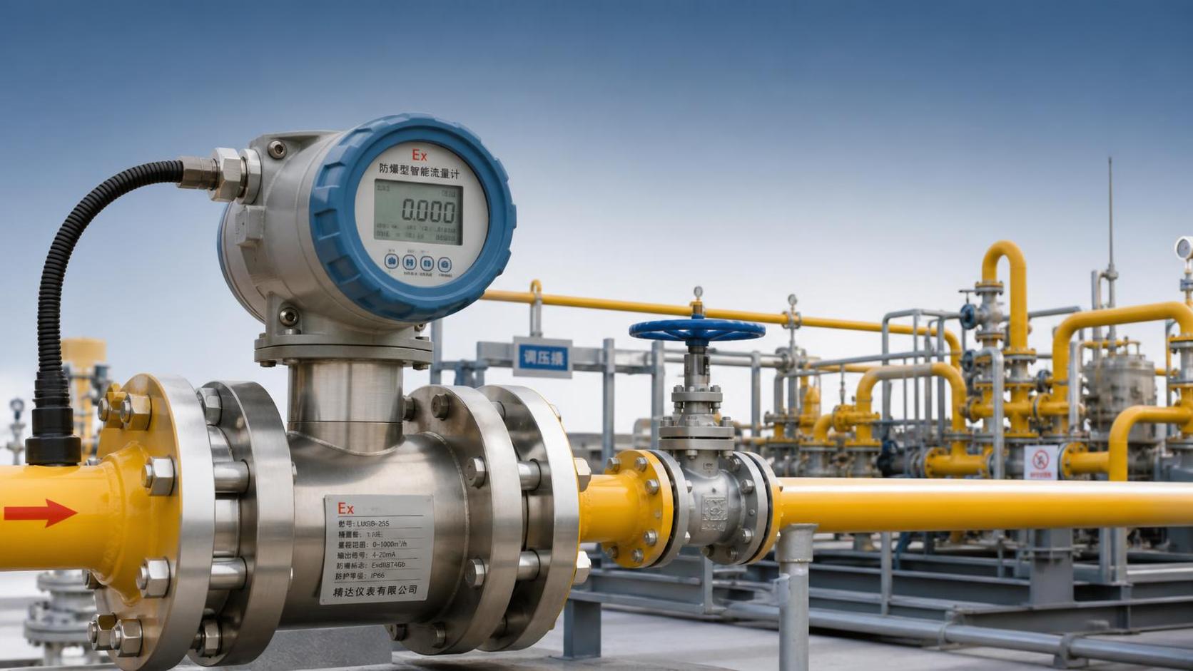
 Why do Xi'an natural gas flowmeters emphasize explosion-proof requirements?
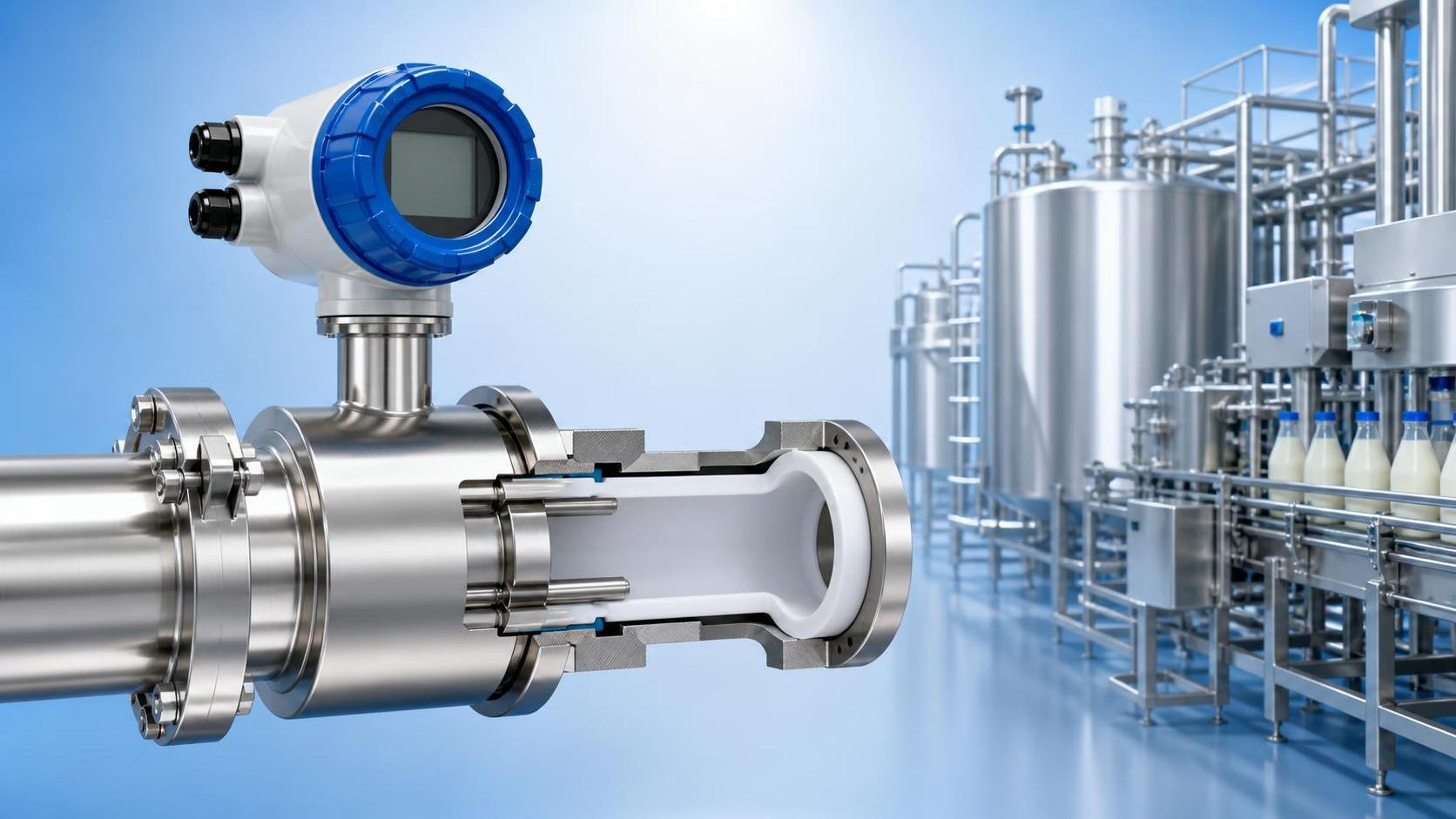
 How to Determine Whether the Material of a Shaanxi Food Flowmeter Meets Standards?
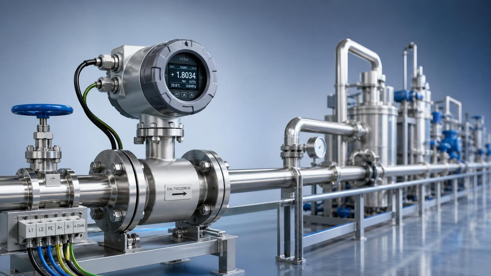
 Is a higher accuracy Xi'an high-precision flowmeter always worth choosing?
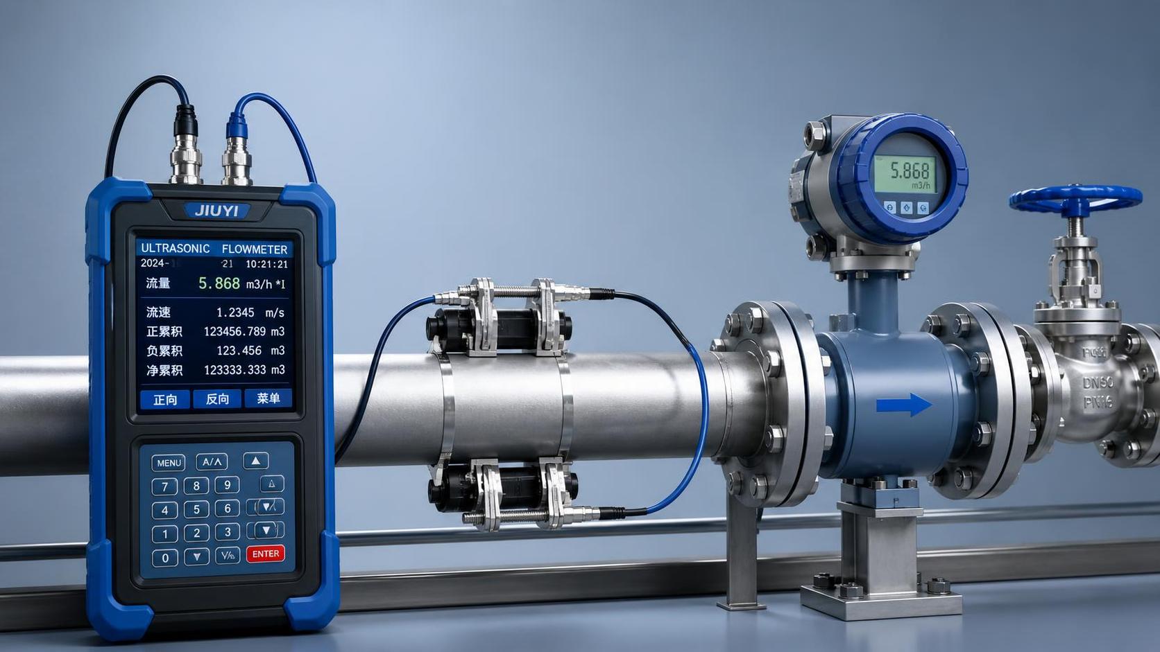
 How to calibrate measurement results of a Shaanxi handheld flowmeter?