News Center
—— NEWS CENTER ——
Xi'an Shenghongchuang Instrument Co., Ltd.
Contact: Mr. Zhang
Mobile: 15529283736
Email: shc-sensor@qq.com
Address: Fortune Building, Sanqiao Street, Xixian New Area, Xi'an, Shaanxi Province
Installation Requirements for Vibration-Resistant Level Sensors: Key Specifications from Installation Location to Commissioning Inspection
Vibration-resistant level sensors are commonly used in pump stations, water tanks, reactors, storage tanks, wastewater treatment equipment, engineering machinery fuel tanks, and automated production lines. Motor vibration, pipeline pulsation, liquid impact, and tank resonance during equipment operation can all cause fluctuations in measurement signals. In severe cases, they may lead to probe loosening, wiring disconnection, or sensor damage.
The core purpose of standardized installation is not only to enable the instrument to display the liquid level, but also to ensure stable measurement, reliable output, and convenient maintenance under long-term vibration conditions. Before installation, comprehensive confirmation should be made based on medium characteristics, vessel structure, liquid level change rate, vibration source location, and control system requirements.
For level sensors with common output types such as 4-20mA, 0-10V, and RS485, mechanical installation, electrical wiring, shielding, and grounding are equally important. If the site focuses only on probe installation depth while neglecting fastening, protection, and signal interference resistance measures, issues such as level signal fluctuation, zero drift, and communication interruption may easily occur later.
I. Operating Conditions and Selection Criteria to Confirm Before Installation
Verify the Medium, Measuring Range, and Process Connection Method
Before installation, first confirm whether the measured medium is corrosive, crystallizable, adhesive, foaming, or high-temperature. Conventional media such as clean water, lubricating oil, and diesel can use standard stainless steel probes; for acidic or alkaline liquids, wastewater, or salt-containing media, particular attention should be given to the resistance capabilities of wetted materials such as 316L, PTFE, and PVDF.
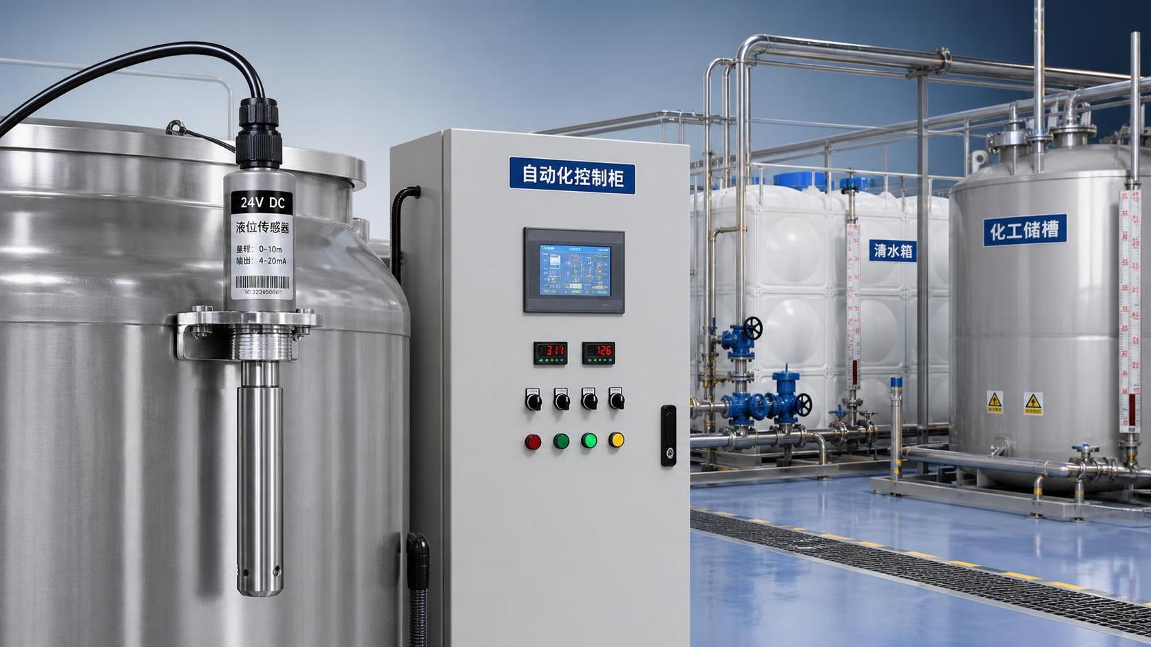
The measuring range should cover the actual liquid level variation range with an appropriate margin. For example, for a submersible level sensor with an actual liquid depth of 8m, a 0-10m range can generally be selected. Long-term operation near full scale is not recommended, in order to reduce the effects of overpressure, liquid impact, and installation deviation on measurement accuracy.
Process connection dimensions, such as flanges, threads, sanitary clamps, or side-mount brackets, must match the on-site interface. Installation personnel should also confirm whether the vessel is pressurized, whether shutdown and pressure relief are required, and whether sufficient space is available around the installation port for wrench operation, wiring maintenance, and sensor installation and removal.
Identify Vibration Sources and Causes of Liquid Level Disturbance
Motors, gear reducers, pumps, agitators, pneumatic valves, and high-speed conveying mechanisms are common vibration sources. Sensors should not be installed directly on equipment support beams with the strongest vibration, near pump outlets, or in resonance areas of thin-walled tanks. Locations with higher structural rigidity and weaker vibration transmission should be selected whenever possible.
When the liquid surface is significantly affected by feed impact, return-flow impact, or agitation vortices, the output value may fluctuate frequently even if the probe is mechanically secured. Under such conditions, it is recommended to install a stilling tube, guide wave tube, or isolated measuring chamber to moderately separate the sensor measurement area from severe disturbances on the main liquid surface.
For sites with high vibration frequency and noticeable impacts, the equipment vibration level and operating cycle should be clearly identified. If the sensor installation location has a large vibration amplitude, metal brackets, vibration-damping pads, or anti-loosening structures may be added. A suitable damping time should also be set in the control system, for example, adjusted between 1 and 5 seconds according to actual fluctuations.
Pre-Installation Checklist
II. Mechanical Installation Requirements for Vibration-Resistant Level Sensors
Avoid Liquid Flow Impact and Structural Resonance Areas
The sensor installation point should avoid locations directly below liquid inlet pipes, near discharge outlets, and around pump suction inlets. High-speed liquid inflow can create localized surface turbulence and pressure pulsation, causing large short-term changes in level sensor output that the control system may misinterpret as an abnormal liquid level.
In equipment such as agitated tanks and circulation tanks, the sensor should preferably be arranged on the side away from the impeller and return-flow port. If no stable liquid surface area can be found inside the tank, a perforated stilling tube may be used for protection. The opening direction should avoid the main liquid flow, and the hole diameter and quantity should balance liquid level response speed and buffering performance.
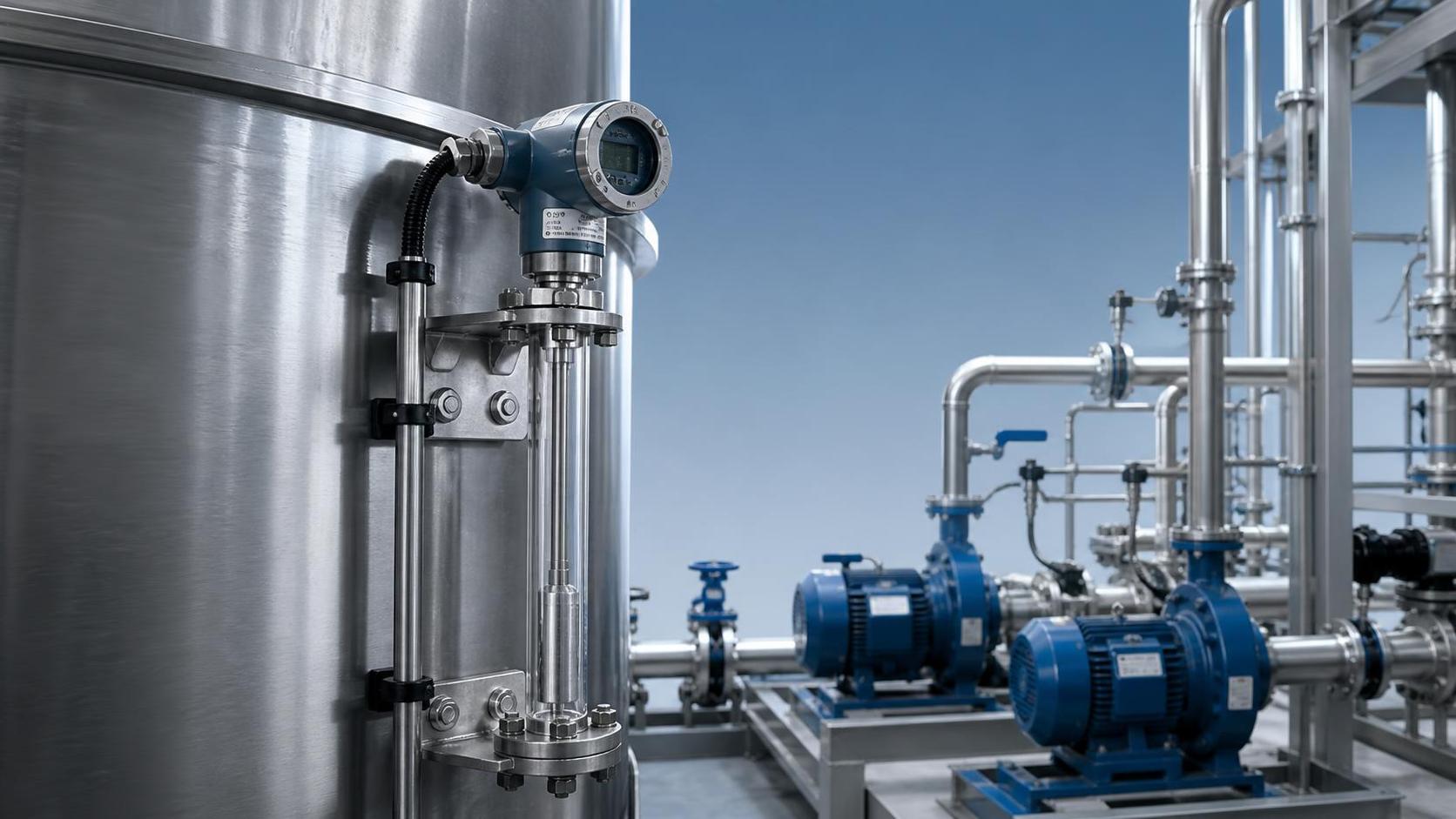
For top-mounted submersible level sensors, the probe must not swing freely for extended periods. Where the liquid level is deep or liquid flow is significant, a counterweight, positioning ring, or guide tube should be added below the probe to prevent repeated cable movement from causing sheath wear and fatigue breakage of internal conductors.
Ensure Fastening, Anti-Loosening Measures, and Cable Securing
When installing threaded level sensors, sealing components matching the interface specifications should be used, and tightening torque should be controlled according to the product manual. Excessive tightening may damage threads, sealing gaskets, or housings, while insufficient tightening can easily result in leakage and loosening due to vibration.
For continuously vibrating equipment, spring washers, lock nuts, thread-locking adhesive, or double-nut structures should be prioritized. Brackets should be secured to rigid structures and should not rely solely on thin plates, guardrails, or temporary steel pipe supports, in order to reduce continuous stress on the sensor body.
A fixing point should be provided before the cable enters the junction box. It is recommended to install a reliable cable clamp every 0.5m to 1m to prevent the cable weight from acting entirely on the connection point. The cable should retain an appropriate allowance to form a drip loop, but must not be coiled too tightly or come into direct contact with high-temperature pipes or sharp edges.
Recommended Vibration-Resistant Measures for Different Installation Types
III. Electrical Connection and Anti-Interference Installation Specifications
Confirm Power Supply Polarity and Output Signal Compatibility
Before wiring, confirm the power supply range, output type, and terminal definitions indicated on the nameplate. Common 24VDC-powered level sensors should use a stable DC power supply, and the supply voltage must fall within the permitted product range. Reversed positive and negative connections may result in no output or damage.
For 4-20mA two-wire products, the total loop load should be calculated to prevent the combined voltage drop of PLC input resistance, isolators, display instruments, and cables from exceeding the permitted load. For sites with transmission distances exceeding 50m, cable cross-section and power supply margin should be checked carefully to prevent insufficient loop voltage at full-scale output.
RS485 communication level sensors should use shielded twisted-pair cables, and the definitions of terminals A and B should be confirmed according to the equipment instructions. When the bus is long or there are many field devices, terminal resistors may be installed at the end of the communication trunk line as required by the system to reduce reflection interference and communication packet loss.
Cable Routing Should Be Kept Away from High Power and Variable-Frequency Interference
Sensor signal cables should not be routed in the same trough in parallel for extended distances with 380V power cables, variable-frequency drive output cables, welding machine cables, or high-power solenoid valve circuits. Where crossing is necessary, a 90-degree crossing arrangement should be used whenever possible to avoid induced interference caused by long-distance parallel routing.
The shielding layer grounding method should remain consistent with the control system design. In general, the shielding layer of analog signals should be grounded at one end, preferably on the control cabinet side, to prevent ground loop currents caused by grounding at both ends. Specific implementation should still comply with the on-site grounding system and product wiring instructions.
Junction boxes, cable connectors, and conduits should provide the corresponding protection capability. For outdoor, humid, or washdown areas, a protection configuration no lower than IP65 is recommended. After tightening connectors, check whether the sealing ring is correctly positioned to prevent condensate from entering the housing along the cable.
IV. Commissioning and Routine Inspection Key Points
Verify at Empty, Full, and Operating Liquid Levels
After installation is complete, first inspect the sensor appearance, mounting bracket, fasteners, cable fixing points, and wiring terminals. After confirming that there is no leakage, looseness, or cable pinching, connect the power supply for signal testing. Avoid repeatedly removing and installing terminals while energized.
During commissioning, record the corresponding display value or output current at low, intermediate, and high liquid levels. A 4-20mA signal should be close to 4mA near the lower range limit and close to 20mA near the upper range limit. If deviation persists, check the range setting, installation depth, medium density, and control system conversion parameters.
Output trends should be observed under actual operating conditions, such as normal equipment vibration, pump unit startup, and agitator operation. If instantaneous fluctuations are large, first confirm whether the mechanical fastening and installation location are appropriate, then set filtering or damping according to process control requirements. Do not rely solely on software filtering to conceal installation issues.
Establish Periodic Maintenance Records
Under vibration conditions, it is recommended to inspect external fasteners, connector sealing, and cable sheath condition every 1 to 3 months. For applications involving high-frequency operation, high temperature and pressure, or corrosive media, the inspection interval should be appropriately shortened according to the equipment maintenance cycle.
Submersible level sensors should be regularly checked for sludge, crystallized material, or fibrous impurities adhering to the probe surface. During cleaning, methods suitable for the diaphragm material should be used. Do not scrape the sensitive diaphragm with hard metal tools, as this may cause irreversible zero offset.
It is recommended to conduct comparative calibration every 6 to 12 months in accordance with on-site metrological requirements. For level measurement points used for interlocking, overflow protection, or critical process control, complete records should be established to document the installation date, calibration results, fault symptoms, repair measures, and replaced component information.
Troubleshooting Directions for Abnormal Conditions After Commissioning
If the liquid level display fluctuates frequently, first check whether the probe is located in a liquid flow impact area, whether the bracket is loose, whether the cable is swinging, and whether the signal cable is close to a variable-frequency drive or power cable. Mechanical issues and electromagnetic interference may coexist and need to be eliminated one by one.
If the output remains consistently high or low, check zero calibration, range settings, the sensor installation reference plane, changes in medium density, and diaphragm deposits. For sealed vessels, also verify whether the vapor-phase pressure compensation method is correct to avoid mistaking pressure changes for liquid level changes.
If intermittent signal loss occurs after the equipment has been operating for a period of time, focus on checking terminal crimping, cable bending points, water ingress at connectors, and power supply stability. For equipment subject to long-term vibration, cable-to-connector connections are frequent failure points and should be a key focus of field inspections.
V. Implementation Recommendations for Long-Term Stable Level Measurement
Installation of vibration-resistant level sensors should follow the sequence of “analyze operating conditions first, determine the location next, then complete fastening and wiring.” A suitable installation location can reduce liquid level disturbances, reliable mechanical fixing can reduce vibration damage, and standardized electrical installation can ensure continuous and stable signals.
For projects involving strong vibration, medium corrosion, liquid surface fluctuation, or long-distance transmission requirements, it is recommended to provide vessel dimensions, medium parameters, temperature and pressure, installation method, supply voltage, and control system interface information before procurement, so that the appropriate measuring range, material, output type, and protection configuration can be determined.
Xi'an Shenghongchuang Instrumentation Co., Ltd. can provide level sensor selection, recommendations for non-standard installation structures, signal support, and technical services based on site conditions in water conservancy, chemical processing, machinery manufacturing, logistics and warehousing, and automated production lines. Before project implementation, on-site operating condition parameters may be submitted to obtain a targeted vibration-resistant level measurement installation solution.