News Center
—— NEWS CENTER ——
Xi'an Shenghongchuang Instrument Co., Ltd.
Contact: Mr. Zhang
Mobile: 15529283736
Email: shc-sensor@qq.com
Address: Fortune Building, Sanqiao Street, Xixian New Area, Xi'an, Shaanxi Province
Basic Requirements for High-Accuracy Level Sensor Calibration
The core of high-accuracy level sensor calibration is to establish a stable and traceable relationship between the instrument output and the actual liquid level. Whether using submersible level transmitters, hydrostatic level sensors, or differential-pressure level measurement devices installed on closed vessels, the measurement principle, measuring range, medium density, power supply method, and output signal type should be confirmed before calibration. Most industrial sites commonly use 24VDC power supply and 4-20mA output, while some devices use RS485 or 0-10V signals. Calibration equipment must match the signal type.
Before formal calibration, first inspect the sensor appearance, leads, wiring terminals, protective interfaces, and installation position. For equipment operating for extended periods in water reservoirs, sewage wells, chemical storage tanks, or underground liquid tanks, particular attention should be paid to probe fouling, blocked vent cables, deposits on isolation diaphragms, and aging sealing rings. If the sensor body has mechanical damage, excessive zero drift, or obvious output fluctuations, the fault should be addressed before accuracy calibration is performed.
The calibration environment should be kept as stable as possible. The ambient temperature is recommended to be controlled at around 20°C, with temperature variation not exceeding ±5°C. For level sensors with an accuracy class of 0.25 or higher, the accuracy of the pressure source, reference instrument, and ammeter used for calibration should generally be at least three times higher than that of the instrument being calibrated. Powering on and preheating for 15 to 30 minutes before calibration can reduce the impact of electronic component temperature drift on the results.
Key Parameters to Confirm Before Calibration
Standard Calibration Procedure: Point-by-Point Verification from Zero to Full Scale
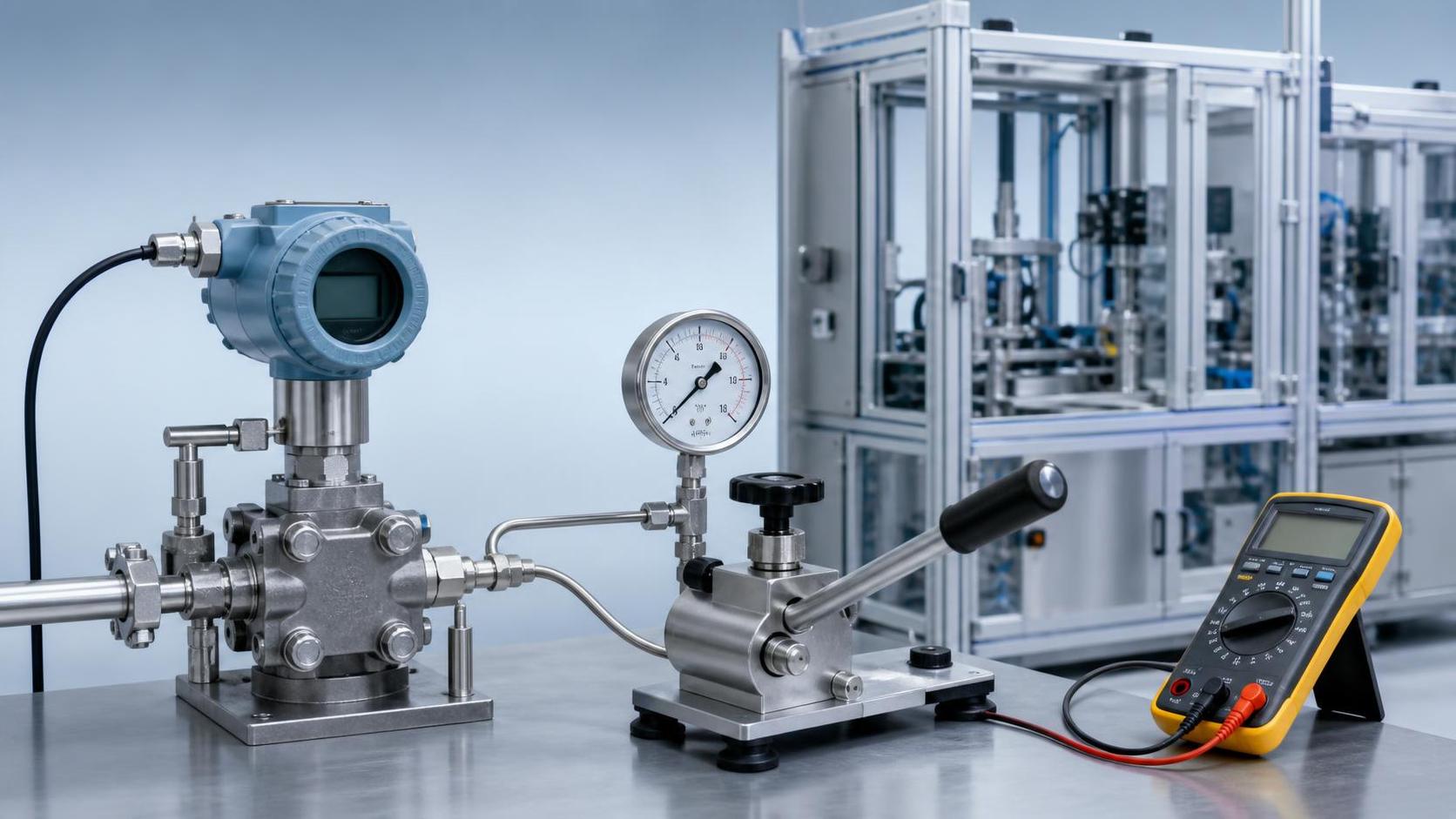
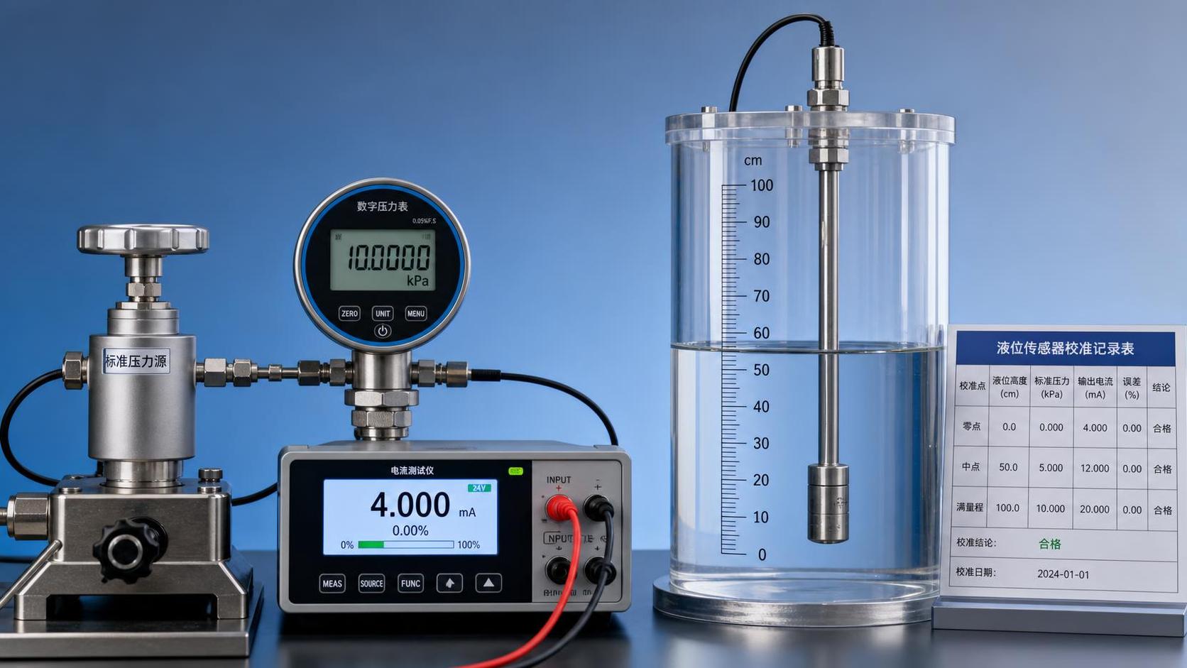
Hydrostatic level sensors are typically calibrated using a pressure calibration method. First, correctly connect the sensor to a standard pressure source, digital pressure gauge, and ammeter, then read the output under no-pressure conditions or at the corresponding minimum liquid level. For 4-20mA products, the theoretical zero output should be 4.000mA. If the allowable error is calculated as 0.5% of full scale, the upper error limit for a 10m range must be determined uniformly after pressure conversion and cannot be judged solely by visual observation of the displayed value.
Then apply load step by step at 25%, 50%, 75%, and 100% of the measuring range. After each pressure point stabilizes, record the standard value and actual output value. Taking a 0-10m level range as an example, liquid levels of 2.5m, 5m, 7.5m, and 10m can be simulated respectively. After completing the upscale test, conduct a downscale test in the sequence of 100%, 75%, 50%, 25%, and 0% to check sensor hysteresis, repeatability, and return error.
If the instrument supports adjustment through local buttons, a magnetic rod, HART communication, or host computer software, zero and span corrections should preferably be performed after confirming authorization. During adjustment, calibrate zero first, then full scale, and then repeat the test at intermediate points. An instrument should not be judged qualified directly after a single adjustment. Generally, at least 2 consecutive cycles should be tested, and the output difference at the same test point between the two cycles should be within the range permitted by the product technical specifications.
For submersible level sensors directly immersed in liquid, an actual level comparison method may also be used. A verified level gauge, radar level meter, or transparent ruler should be selected as a reference to avoid surface fluctuations, bubble adhesion, and severe changes in liquid temperature. During on-site tank calibration, it is recommended to read data after the liquid level has stabilized for 3 to 5 minutes, especially for water conservancy projects, wastewater treatment tanks, and large raw-material tanks.
Example of a Five-Point Calibration Record
Error Control: Identifying Factors That Affect Measurement Accuracy
Level measurement errors do not come entirely from the sensor itself. Hydrostatic measurement is affected by medium density. When water temperature, concentration, or mixing ratio changes, the pressure generated at the same liquid level also changes. For example, when density changes from 1.00g/cm³ to 1.10g/cm³, the theoretical pressure changes by approximately 10%. If conversion is still performed using the original density, the displayed liquid level will show a significant deviation. Therefore, density correction should be included in calibration records for applications involving chemical media, salt water, slurry, and similar media.
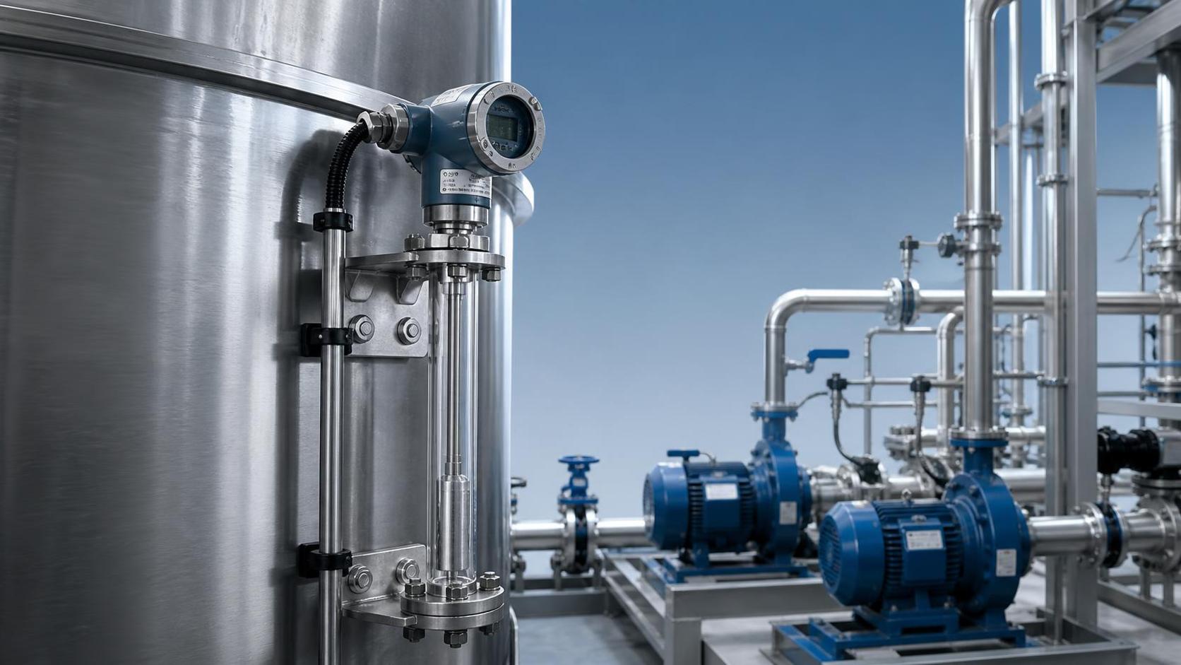
In closed tanks, gas-phase pressure directly affects the readings of ordinary hydrostatic sensors. Differential-pressure level transmitters should be used for such conditions, introducing the tank-bottom pressure and tank-top gas-phase pressure separately to eliminate vessel pressure interference through differential pressure. Impulse lines should be protected from liquid accumulation, blockage, and leakage. Installation slope, heat-tracing conditions, and condensate pot status can all affect the final calibration results.
Where variable-frequency drives, motors, and high-power switching equipment are present on site, shield grounding and power supply ripple should be checked. Independent shielded cables are recommended for 4-20mA loops, avoiding long-distance parallel routing with power lines; when wiring must cross, a 90-degree angle should be maintained as much as possible. If signal fluctuations exceed the normal process fluctuation range, electromagnetic interference, poor grounding, and abnormal supply voltage should first be ruled out before determining whether recalibration is required.
Maintenance and Recalibration Intervals Under Different Operating Conditions
The maintenance interval for water conservancy level sensors should be determined based on water quality, installation depth, seasonal changes, and operational importance. For general applications such as clean-water reservoirs, channels, and water tanks, comparison calibration is recommended once every 6 to 12 months. Inspections should be increased before the rainy season, before flood season, and when operation resumes after a prolonged shutdown. Separate records should be established for measurement points used for level interlocks, pump start/stop control, or overflow alarms.
For corrosive media such as strong alkalis, acidic wastewater, and saline wastewater, attention should be given to the resistance of isolation diaphragms, housing materials, and seals. When using corrosion-resistant level sensors, replacement should not be scheduled solely according to nominal service life; it should be determined based on the actual degree of corrosion, drift trends, and cleaning frequency. If slow output response, unstable zero point, diaphragm crystallization, or housing pitting occurs, the recalibration interval should be shortened and replacement needs should be evaluated.
At pump stations with strong vibration, near mechanical equipment, and on mobile storage tanks, inspect sensor mounting brackets, cable tension, and loose interfaces. When installing vibration-resistant level sensors, avoid direct impact areas and maintain an appropriate distance between the probe and the tank bottom to prevent sediment coverage. After each maintenance operation, zero point, alarm thresholds, and control-system display values should be verified to avoid inconsistencies between field instruments and PLC data.
Calibration Acceptance Criteria and Technical Service Support
After calibration is completed, the standard instrument identification number, ambient temperature and humidity, test medium, calibration points, upscale and downscale data, allowable error, and final conclusion should be fully documented. For Class 0.5 level sensors, the allowable full-scale error is generally used as the basis for determination. If the customer's process is more sensitive in the low-level range, control requirements for the 0% to 20% range should also be agreed separately to avoid inaccurate low-level control despite passing full-scale requirements.
If a significant deviation remains after calibration, repeated forced adjustment is not advisable. The installation height reference, medium density setting, pressure transmission path, supply voltage, display instrument range, and proportional conversion relationship of the control system should be verified in sequence. For systems equipped with intelligent digital display control instruments, the decimal point position, alarm upper and lower limits, and filtering time parameters must also be confirmed to prevent correct sensor operation but erroneous display or interlock logic.
Xi'an Shenghongchuang Instrumentation Co., Ltd. can provide level sensor selection, calibration recommendations, non-standard customization, and technical service support for applications such as storage tanks, water conservancy, chemical processing, and automated production lines. If existing level measurement points experience data drift, frequent alarms, corrosion damage, or unstable control, please compile information such as measuring range, medium, temperature, pressure, power supply, and site photos. Professional technical personnel will verify the operating conditions and develop an appropriate solution.