News Center
—— NEWS CENTER ——
Xi'an Shenghongchuang Instrument Co., Ltd.
Contact: Mr. Zhang
Mobile: 15529283736
Email: shc-sensor@qq.com
Address: Fortune Building, Sanqiao Street, Xixian New Area, Xi'an, Shaanxi Province
How Far Can an RS485 Level Sensor Transmit? Communication Distance, Wiring Methods, and Key Points for Stable Operation
In projects such as tank level monitoring, wastewater treatment, chemical batching, and smart warehousing, RS485 level sensors are widely used due to simple wiring, good anti-interference capability, and connectivity to PLCs and host computers. In actual projects, the question of “how far can it transmit” cannot be determined solely by a single figure in the product manual; baud rate, communication cable, number of nodes, on-site electromagnetic environment, and terminal matching must all be considered comprehensively.
Generally, level sensors using a standard RS485 communication interface can achieve a low-speed communication distance of approximately 1,200 meters under compliant wiring conditions, with shielded twisted-pair cable and a properly designed network topology. If frequency converters, motors, welding equipment, or high-voltage cables are present on site, the stable distance may be significantly reduced. Communication quality may need to be improved by lowering the baud rate, adding isolators, or installing repeaters.
The measurement accuracy and communication stability of level sensors are equally important. For applications requiring continuous level recording, pump and valve interlocking, or high- and low-level alarm triggering, the transmission distance, number of devices, power supply method, and protocol requirements should be defined at the initial project stage to avoid data distortion or delayed control actions caused by communication disconnections later on.
I. Theoretical Transmission Distance of RS485 Level Sensors
Distance Is Directly Related to Baud Rate
RS485 uses differential signal transmission, where voltage changes on the two communication wires occur in opposite directions. The receiving end identifies data by detecting the voltage difference, making it more suitable for industrial sites than single-ended signals. Under standard conditions, an RS485 bus can typically achieve an effective communication distance of 800 to 1,200 meters at around 9600bps.
As the baud rate increases, signal edges become faster, and the effects of cable distributed capacitance and signal attenuation on communication also increase. For example, 115200bps is generally more suitable for distances ranging from tens of meters to several hundred meters. If the line reaches several hundred meters or more, 2400bps, 4800bps, or 9600bps is usually recommended, subject to on-site test results.
It should be noted that 1,200 meters is an ideal engineering reference value and does not mean that stable communication can be achieved with any cable in any environment. When level sensors are installed in underground water tanks, beside steel storage tanks, in pump rooms, or in mining areas, environmental humidity, grounding conditions, and electromagnetic interference all affect the actual usable distance.
During engineering selection, it is recommended to reserve a 20% to 30% margin for communication distance. For example, if the actual cable length is 700 meters, it should not be assessed solely on the basis that the “theoretical transmission distance is 1,000 meters.” It is also necessary to verify whether it runs parallel to power cables, whether there are multiple branches, and whether the device power supply is stable.
II. Four Key Factors Affecting Communication Distance
Cable Specifications Determine the Signal Foundation
For level sensor communication lines, shielded twisted-pair cable with a characteristic impedance of 120 ohms is recommended. The conductor size can be determined according to line length and power supply requirements. For standard data acquisition lines within 300 meters, shielded twisted-pair cable of approximately 0.5 mm² is commonly used. For longer distances or simultaneous power transmission, the conductor cross-sectional area should be increased appropriately.
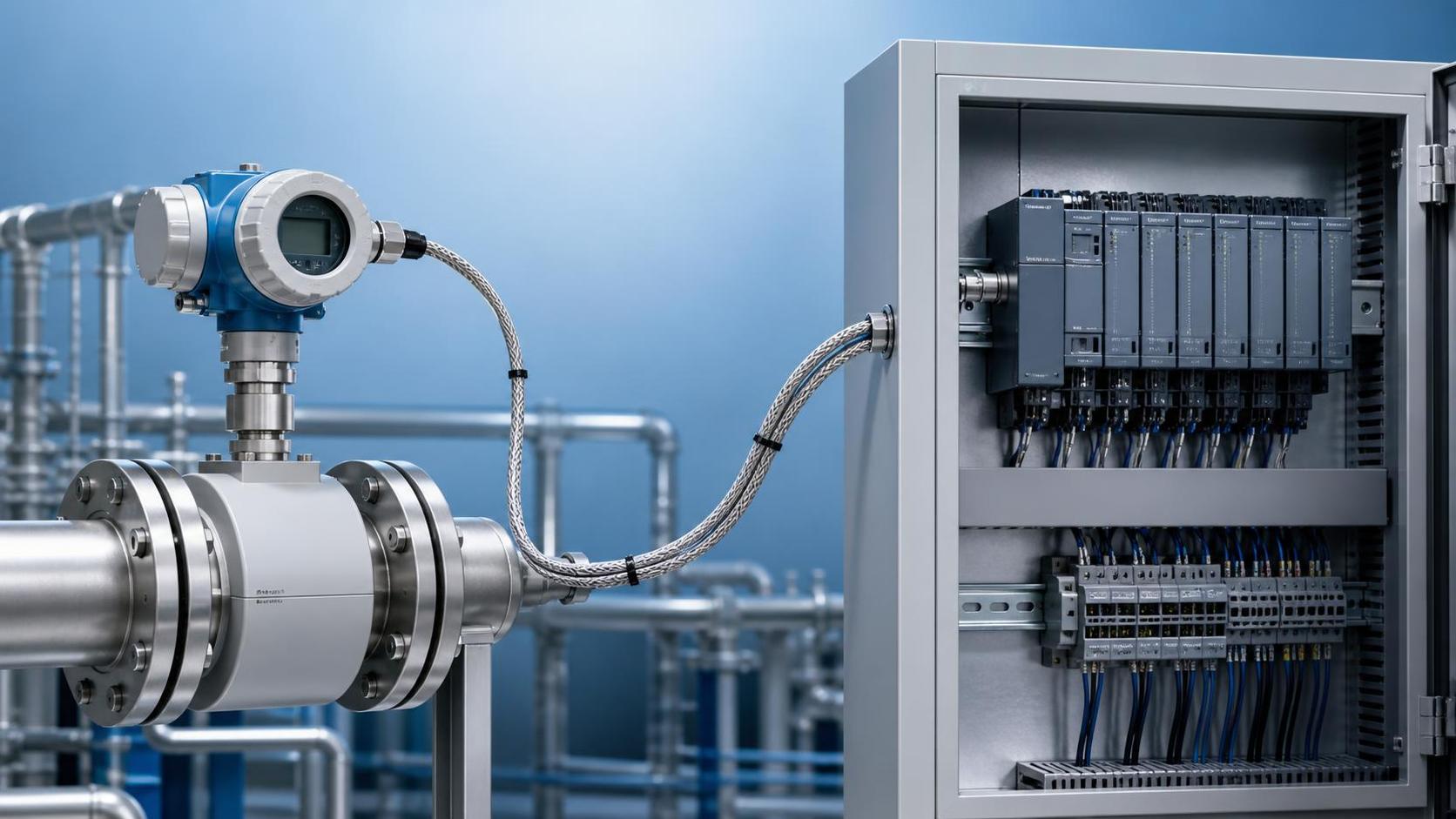
Ordinary parallel cables do not have a twisted-pair structure and are prone to absorbing external electromagnetic interference. Unshielded cables are also more likely to cause communication timeouts, data fluctuations, and device offline issues when used near frequency converters, inside power cabinets, or in plant cable trenches. The shield layer should be reliably grounded at one end to avoid ground loop currents.
If the level sensor uses a 24VDC power supply, voltage drop in the power cable should also be calculated. Taking a 500-meter line as an example, if the wire size is too small and there are many devices, the operating voltage at the far end may fall below the sensor's rated range. This may appear as unstable communication, while the actual cause is insufficient power supply.
In areas with high humidity, outdoor exposure, or corrosive gases, the outer cable jacket and junction box sealing rating must also not be overlooked. Water ingress into communication lines, terminal oxidation, or damage to the shield layer can all increase line impedance and reduce the stable transmission distance of RS485 level sensors.
Network Topology Affects Bus Quality
RS485 level sensors should use a daisy-chain bus topology, connecting devices in sequence from the PLC, data acquisition unit, or gateway. Star wiring creates multiple signal reflection points. It may operate normally when there are few devices and short distances, but it can easily cause intermittent faults in long-distance networks.
A 120-ohm termination resistor is generally required at both ends of the bus to absorb reflected signals. More termination resistors are not necessarily better. Under normal conditions, they should only be installed at the beginning and end of the line. Repeatedly connecting termination resistors at intermediate nodes increases bus load and instead reduces signal amplitude.
In traditional designs, a single RS485 bus can connect approximately 32 standard nodes. The actual number of connectable devices also depends on the sensor interface chip, communication frequency, and cable length. When there are 20 to 30 level sensors, it is recommended to plan addresses centrally, avoid address duplication, and appropriately extend the host polling cycle.
For projects exceeding 1,000 meters or spanning workshops or buildings, isolated RS485 repeaters can be added in the middle to divide the network into multiple independent segments. Repeaters can extend distance and reduce the node load of each segment, making subsequent troubleshooting easier in complex industrial environments.
III. How to Select Configurations for Different Site Conditions
Determine the Solution Based on Site Distance and Interference Level
For water tanks, material silos, or clean-water tanks in ordinary factory buildings, if the distance between the sensor and PLC is within 100 meters, 9600bps, shielded twisted-pair cable, and standard bus wiring can generally meet long-term operating requirements. The key points for such projects are ensuring consistent A and B line polarity and registering each device communication address individually.
For tank farms, wastewater stations, or production workshops with distances from 200 to 600 meters, it is recommended to reduce the baud rate to 4800bps or 9600bps and maintain a distance of at least 30 cm between communication lines and power lines. Where crossing is necessary, a near-90-degree crossing method should be used to reduce induced interference caused by long parallel runs.
In high-interference environments such as chemical plants, metallurgical facilities, and mines, isolated RS485 interfaces should be prioritized in addition to shielded twisted-pair cable. Isolation design can reduce the impact of ground potential differences between devices, providing practical value in protecting PLC communication ports and improving level data continuity.
For locations spanning buildings, outdoor long-distance installations, or areas with frequent lightning activity, communication surge protectors should be installed before the line enters the control cabinet. For applications exceeding 1,200 meters, fiber-optic conversion, industrial wireless gateways, or distributed data acquisition stations may be considered. Extending copper cables alone should not be relied upon to solve the issue.
IV. Commissioning and Troubleshooting Methods for Level Monitoring Projects
Check Basic Items First When Communication Is Unstable
When an RS485 level sensor occasionally goes offline, first check the sensor power supply voltage, A/B communication line polarity, and communication parameters. The address, baud rate, parity bit, data bits, and stop bits of the master and slave stations must be fully consistent. Any mismatch may prevent data from being read.
Next, disconnect some nodes and test in sections to determine whether the fault is concentrated in a specific line segment. If the network recovers after disconnecting one sensor, check that device's wiring and whether there is an address conflict, as well as whether there are issues such as moisture, loose connections, or incorrect shield grounding in the junction box.
If level readings are occasionally abnormal but communication has not been interrupted, it is also necessary to distinguish between a transmission issue and a measurement issue. Raw values can be read at the sensor end and compared with values displayed at the PLC end. If the data at both ends are consistent, further inspection should be made of the installation position, medium fluctuations, probe fouling, or range settings.
Before project acceptance, continuous operation for 24 to 72 hours is recommended, with communication success rate, alarm response, and level trends recorded. For important storage tanks, communication interruption alarms and upper/lower level interlocks can be configured to ensure that sensor abnormalities, line faults, or controller offline conditions are detected and addressed promptly.
V. What Information Should Be Confirmed When Selecting an RS485 Level Sensor?
Before selection, provide the medium name, measurement range, temperature, pressure, installation method, and vessel structure. Clean water, wastewater, acidic and alkaline liquids, oils, and high-viscosity media have different requirements for probe materials and measurement principles, so products cannot be selected based only on the communication interface.
For communication, it is necessary to specify whether Modbus RTU or another protocol is used, the PLC brand and model, the expected line length, and the number of devices. For systems that also need to connect instruments for pressure, flow, temperature, humidity, and other parameters, address planning and polling logic should be standardized to support future expansion of the automation control system.
For high-temperature, high-pressure, highly corrosive, or hazardous areas, confirm the level sensor's protection rating, temperature resistance range, process connection type, and explosion-proof requirements. A product body suitable for on-site conditions is only the first step toward reliable operation; proper cables, grounding, and installation also determine project service life.
Xi'an Shenghongchuang Instrumentation Co., Ltd. can provide selection recommendations for RS485 level sensors, matching transmitters, and intelligent digital display control instruments based on site distance, medium characteristics, control system, and installation conditions. By providing the range, medium, temperature and pressure parameters, transmission distance, and PLC model, a more suitable communication and measurement-control solution can be further determined.
Related Recommendations
 How to Select an Industrial Flowmeter in Xi'an Based on Operating Conditions?
 What on-site measurements are Shaanxi portable flowmeters suitable for?
 What Costs Should Be Considered When Purchasing Small Flowmeters in Xi'an?
 How can Shaanxi remote-transmission flowmeters reduce signal transmission errors?