News Center
—— NEWS CENTER ——
Xi'an Shenghongchuang Instrument Co., Ltd.
Contact: Mr. Zhang
Mobile: 15529283736
Email: shc-sensor@qq.com
Address: Fortune Building, Sanqiao Street, Xixian New Area, Xi'an, Shaanxi Province
Pre-Installation Operating Condition Verification for Low-Pressure Flow Meters in Xi'an
Low-pressure flow meters are commonly used in water supply and drainage, HVAC circulation, compressed air, environmental treatment, equipment integration, and automated production lines. Before installation, confirm the medium type, temperature, operating pressure, instantaneous flow rate, pipe diameter, and output signal. Do not select and install a meter solely based on the pipe size. In low-pressure systems, even minor pressure loss, air bubbles, and flow velocity fluctuations may cause measurement deviations.
Verify that the flow meter range matches the actual on-site flow rate. It is generally recommended that the normal flow rate remain within 30% to 80% of the instrument range. This helps obtain stable readings and prevents insufficient resolution caused by long-term low-flow operation. If the system has intermittent liquid supply, frequent start-stop operation, or significant flow peaks, determine the range based on the actual peak flow and stable operating conditions.
For low-pressure liquid pipelines, also confirm whether the medium contains suspended particles, fibers, oil contamination, crystalline substances, or corrosive components. For media containing impurities, install a filter upstream of the flow meter. The filtration accuracy should be determined according to the instrument structure and particle size in the medium. For media prone to scaling, allow sufficient space for disassembly, flushing, and maintenance.
At some industrial sites in Xi'an, day-night temperature differences can be significant. For outdoor or semi-outdoor installations, consider winter freeze protection, summer sun protection, and the effects of condensate. The instrument enclosure protection rating, power supply conditions, and cable weather resistance should be compatible with the site environment to prevent environmental factors from affecting the long-term stable operation of the sensor.
Verification Items and Installation Impacts
Confirm Instrument Direction and Full-Pipe Conditions
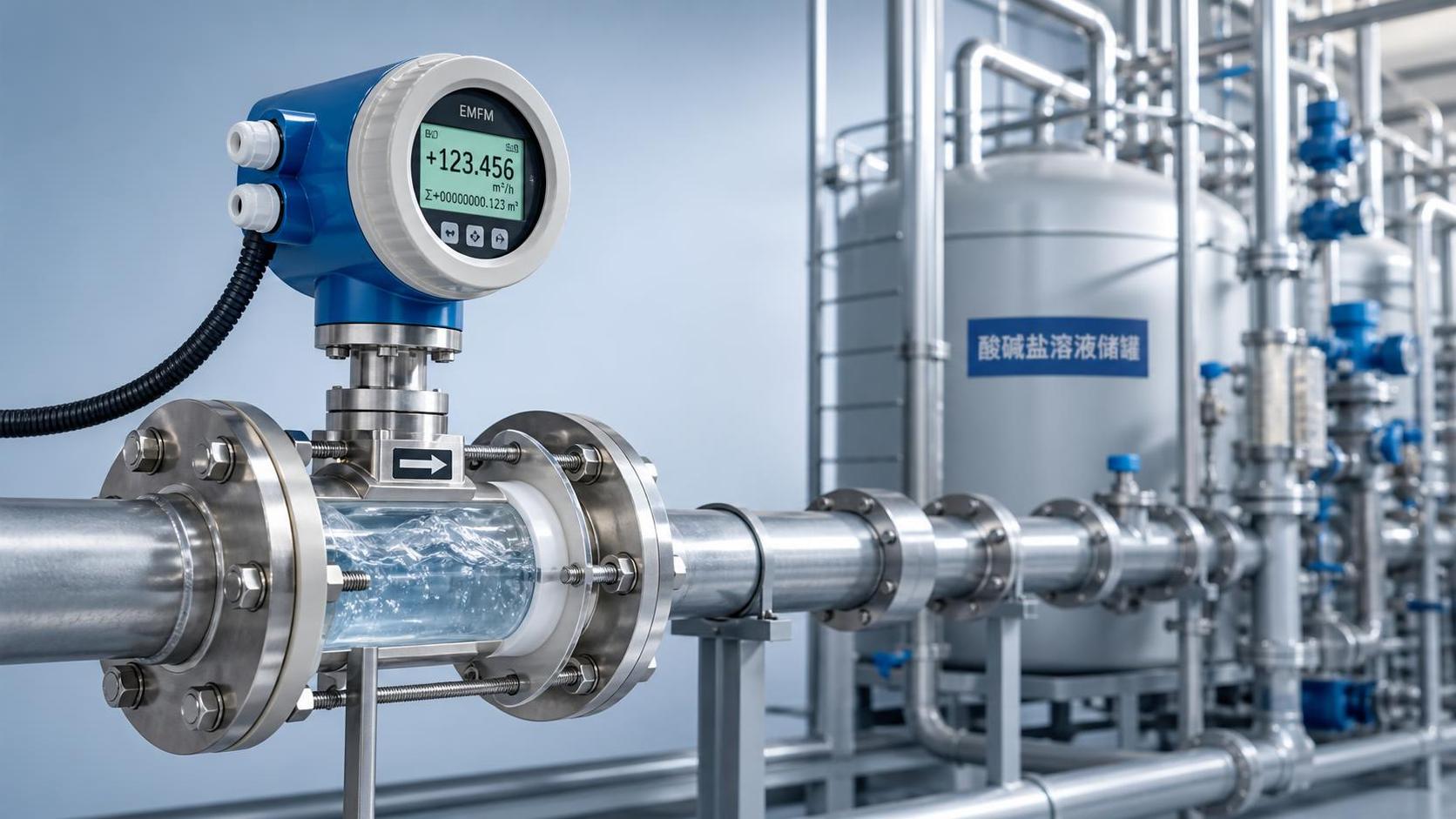
The flow meter body is typically marked with an arrow. During installation, ensure that the arrow direction is consistent with the actual flow direction of the medium. Reverse installation may cause an incorrect totalized flow direction, abnormal instantaneous values, and alarms on some products. Even if the control system can correct a reverse signal, software compensation should not replace proper installation.
For electromagnetic flow meters, ultrasonic flow meters, and most liquid flow measurement devices, the measuring pipe section must remain full. Installation at the highest point of the pipeline, at the outlet of a downward discharge vertical pipe, or at locations prone to air pockets will prevent the sensor from obtaining stable and effective signals. This issue is more pronounced under low-pressure conditions.
For horizontal pipe installation, priority may be given to positioning the sensor on the side of the pipe to prevent electrodes or sensitive components from remaining at the highest point where gas accumulates or at the lowest point where deposits settle. For vertical pipelines, liquid should preferably flow from bottom to top, which helps discharge air bubbles and maintain a full-pipe condition.
If high-point installation cannot be avoided on site, add an air vent valve upstream or optimize the pipeline routing. If the medium contains many air bubbles, first address root causes such as air leakage at the suction inlet, cavitation before the pump, or an excessively low tank level. Do not rely solely on adjusting instrument parameters to solve the issue.
Pipeline Layout and Straight Pipe Section Control
A flow meter measures the fluid condition inside the pipe. Elbows, valves, reducers, tees, pumps, and filters can all alter flow velocity distribution. In low-pressure systems, fluid kinetic energy is inherently low, and disturbances caused by local resistance components take longer to recover. Therefore, straight pipe sections must not be arbitrarily shortened.
The straight pipe section length can generally be determined according to the instrument manual. Where there are no special requirements, the upstream straight pipe section may be controlled at 5D to 10D and the downstream straight pipe section at 3D to 5D, where D represents the nominal pipe diameter. If a double elbow, control valve, pump outlet, or reducer is immediately upstream of the flow meter, the upstream straight pipe section should be appropriately increased.
The installation location should be kept as far as possible from equipment with strong vibration and high-power variable-frequency equipment. Nearby pumps, air compressors, and mixing equipment may cause not only mechanical pipeline vibration but also pressure pulsation and electromagnetic interference. Where necessary, use independent supports, flexible connections, and signal cable shielding measures to reduce the impact.
For process pipelines requiring a bypass, it is recommended to install shutoff valves on both sides of the flow meter and use them together with bypass piping. This allows the system to continue operating during instrument maintenance or calibration and avoids low-pressure leakage, pipeline backflow, and medium backflow during disassembly and installation.
Recommended Spacing for Typical Pipeline Components
Prevent Pipeline Stress from Being Transmitted to the Sensor
Before installing a flanged low-pressure flow meter, check whether the flanges at both ends are parallel and concentric. Do not forcibly align the pipeline by tightening the bolts. Pipeline misalignment can cause the instrument housing, lining, or measuring tube to bear additional stress over time, affecting sealing reliability and zero-point stability.
Large-diameter instruments are heavy and must not be fully supported by the pipelines on both sides. Install a sturdy support near the flow meter, especially for DN80 and above specifications or equipment installed in vibration-prone areas. The support should bear the instrument weight but should not compress the transmitter housing, terminal box, or signal cables.
Where thermal expansion and contraction of the pipeline are significant, fixed supports, guide supports, or compensating structures should be properly arranged. For plastic pipes, thin-wall stainless steel pipes, and high-temperature medium pipelines, take particular care to prevent deformation from pulling on flow meter connections, thereby avoiding leakage or mechanical damage during long-term operation.
After installation, recheck the flange gap, bolt loading, and support loading before introducing the medium. All fasteners should be tightened evenly in several stages in a diagonal sequence. Sealing gaskets must not extend into the inner wall of the pipeline, as this may create local throttling and disturb the flow field.
Low-Pressure Connection, Sealing, and Grounding Details
Although low-pressure systems have relatively low pressure values, sealing quality still directly affects measurement stability due to long operating hours and frequent start-stop cycles. Flange gaskets should be selected according to the medium, temperature, and flange type. Suitable rubber or non-asbestos gaskets may be used for water-based media, while corrosion-resistant materials are required for corrosive media.
For threaded flow meters, avoid allowing excessive PTFE tape or sealant to enter the measuring chamber. After sealing material debris enters the sensor, it may adhere to the impeller, vortex shedder, or measuring channel, resulting in slow readings, jamming, or abnormal zero points.
For electromagnetic flow meters, grounding is a critical installation requirement. The sensor, process pipeline, and control system should be reliably connected for equipotential bonding as required by the product. Plastic pipelines, internally lined insulated pipelines, or cathodically protected pipelines generally require grounding rings or grounding electrodes and must not rely solely on the power supply protective earth.
After installation, first perform a low-pressure hold test and leak inspection, then gradually increase to normal operating conditions. Never loosen flange bolts, unscrew threaded joints, or remove terminal boxes under full pressure. If leakage is found, first shut down, depressurize, and drain the system, then identify causes such as gasket displacement, flange deformation, or insufficient tightening.
Approaches to Common Sealing Issues
If slight liquid seepage occurs at a flange connection, it is not recommended to continue tightening on one side only. After shutdown, check whether the flange faces are scratched, whether the gasket is eccentric, and whether the bolts are evenly loaded. Blindly applying additional force can damage soft gaskets and worsen leakage.
If readings become unstable after the instrument has operated for some time and there is no obvious leakage at the connection, check whether the pipeline is drawing in air. A small leak point on the low-pressure suction side may not cause visible liquid leakage but can continuously draw in air, increasing the gas content of the liquid medium and affecting the flow signal.
Outdoor terminal boxes and cable entries should be arranged downward or toward the lower side to prevent rainwater from entering the enclosure along the cable. Cable glands must be tightened, and unused cable entry holes must be sealed with plugs to prevent moisture ingress that could reduce insulation resistance and corrode terminals.
For workstations requiring long-term continuous operation, incorporate the flow meter number, installation date, initial totalized flow, and inspection records into the equipment register. When abnormal flow is subsequently detected, historical data can help determine whether the issue is due to process changes, pipeline blockage, sensor drift, or signal transmission failure.
Route Signal Cables Separately from Power Cables
Signal cables for 4mA to 20mA, pulse, RS485, and similar signals should use shielded cables and should be routed separately from variable-frequency drive output cables, motor power cables, and high-current busbars whenever possible. Maintain a parallel separation distance of more than 300mm; where crossing is necessary, cross at an angle close to 90 degrees to reduce coupling interference.
The shield grounding method should comply with the instrument manual and control system grounding specifications. In general, single-end grounding of the shield can reduce ground loop interference. Where special explosion-proof requirements, long-distance communication, or complex equipotential systems exist on site, professional technical personnel should determine the method based on the system design.
The power supply voltage must match the value indicated on the nameplate. Before energizing, check the positive and negative terminals, terminal numbers, and fuse protection. For DC 24V powered devices, take particular care to prevent reverse polarity. For AC powered devices, confirm that the neutral, live, and protective earth connections are correct to avoid damaging the conversion module.
After wiring is completed, use a multimeter to check terminal voltage, loop current, and grounding continuity. If the signal is abnormal, first investigate power quality, loose terminals, cable damage, and shield grounding. Do not directly conclude that the flow meter sensor has failed.
Commissioning and Routine Maintenance Essentials
After the low-pressure flow meter is installed, commission it in the sequence of “inspection, venting, gradual pressurization, verification, and recording.” When the medium is first introduced, slowly open the upstream valve to allow air in the pipeline to be gradually discharged. The downstream valve may be used to establish stable back pressure but should not remain in an excessively throttled condition for extended periods.
During the initial commissioning period, observe whether the instantaneous flow, totalized flow, alarm status, and control system display are consistent. For 4mA to 20mA outputs, verify the signal values separately under zero-flow, normal-flow, and near-full-scale conditions to confirm that the range settings, unit settings, and decimal point position are correct.
During normal operation, if the flow value continuously fluctuates, output remains when there is no flow, the flow is low, or the totalized flow is abnormal, assess the issue in combination with on-site valve opening, pump operating status, filter differential pressure, and medium temperature. Instrument and process issues often influence each other, so complete operating records should be retained during troubleshooting.
The maintenance interval should be determined based on medium cleanliness and frequency of use. Clean water and low-viscosity liquids can undergo routine inspection every 6 months to 12 months; media containing impurities, prone to scaling, or subject to frequent start-stop operation should have shorter inspection intervals. Before maintenance, power isolation, process isolation, depressurization, and draining measures must be implemented.
Commissioning Checklist
First inspect the mechanical installation: confirm the correct flow direction, full-pipe condition, no leakage at flange or threaded connections, proper support loading, and that straight pipe sections have not been compromised by subsequent modifications. For smart flow meters with displays, also confirm that the display orientation is convenient for routine inspection and data reading.
Then inspect electrical connections: confirm that the power supply rating, grounding, shield layer, signal polarity, and communication address all meet design requirements. For RS485 communication devices, further verify the baud rate, parity method, and terminating resistor configuration to prevent intermittent disconnection after multiple instruments are connected.
Then verify parameters, including pipe diameter, flow unit, upper and lower range limits, damping time, alarm thresholds, totalized flow unit, and output mode. Range parameters should be consistent with the design drawings and actual on-site operating conditions. After parameter changes, they should be reviewed by operators and documented in change records.
Finally, observe stability: after 15 minutes to 30 minutes of continuous operation, compare the field instrument, PLC display, and host computer data. If fluctuations exceed the process allowable range, first check for air bubbles, valve disturbances, grounding, and electromagnetic interference before deciding whether to perform zero-point calibration or technical maintenance.
Establish Traceable Maintenance Records
It is recommended to establish an individual file for each flow meter, recording the model, diameter, identification number, installation location, medium, range, factory serial number, and commissioning date. For critical metering points, calibration certificates, wiring diagrams, and site photographs may also be added to facilitate rapid confirmation of equipment status during future maintenance.
Routine inspections should focus on whether the display is clear, whether water has entered the enclosure, whether wiring is loose, whether flanges are leaking, and whether flow trends are abnormal. Compared with a single reading, continuous trends are more likely to reveal early issues such as filter blockage, declining pump performance, and pipeline scaling.
When sensor inspection or disassembly is required, use tools compatible with the instrument specifications to avoid impacting the measuring tube, lining, electrodes, or sensitive elements. Removed seals are generally not recommended for reuse. When reinstalling, check alignment, cleanliness, and grounding connections again.
Xi'an Shenghongchuang Instrumentation Co., Ltd. can provide flow meter selection, installation guidance, parameter commissioning, and technical services based on the on-site medium, low-pressure pipeline structure, installation space, and control signal requirements. Before project implementation, it is recommended to submit the pipe diameter, medium, pressure, temperature, flow range, and site photographs. Installation and commissioning should be carried out after professional personnel confirm the suitable solution.
Related Recommendations
 What Details Should Be Noted When Installing a Low-Pressure Flowmeter in Xi'an?
 What Parameters Should Be Considered When Selecting a Shaanxi High-Pressure Flow Meter?
 What Problems May Arise from Long-Term Use of High-Temperature Flowmeters in Shaanxi?
 What Media Are Xi'an Corrosion-Resistant Flowmeters Suitable for Measuring?